Drilling the horizontal stabilizer 6h
6h
May 11, 2022
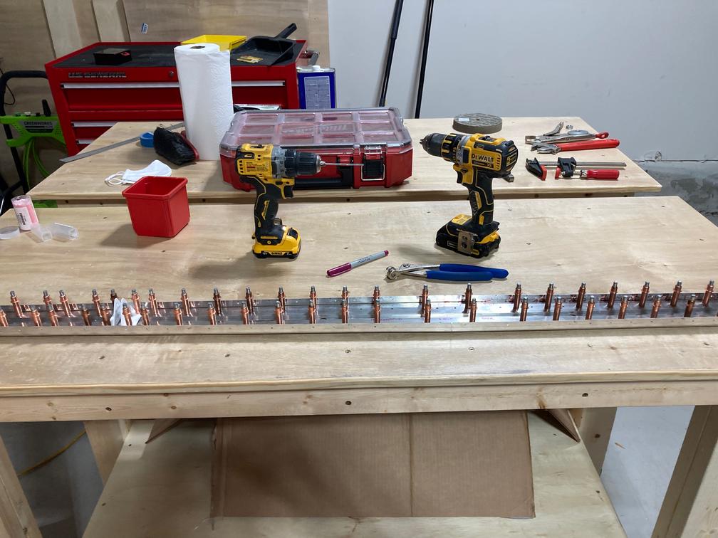
Started working on the horizontal stabilizer.
I put the vertical stabilizer aside until I figure out what to do about it, and started working on the horizontal stabilizer.
The first step was to round the corners of rear spar reinforcement bars to make sure they fit into the rear spar. Then I used Scotch-Brite for both the spar itself and the reinforcement bars.
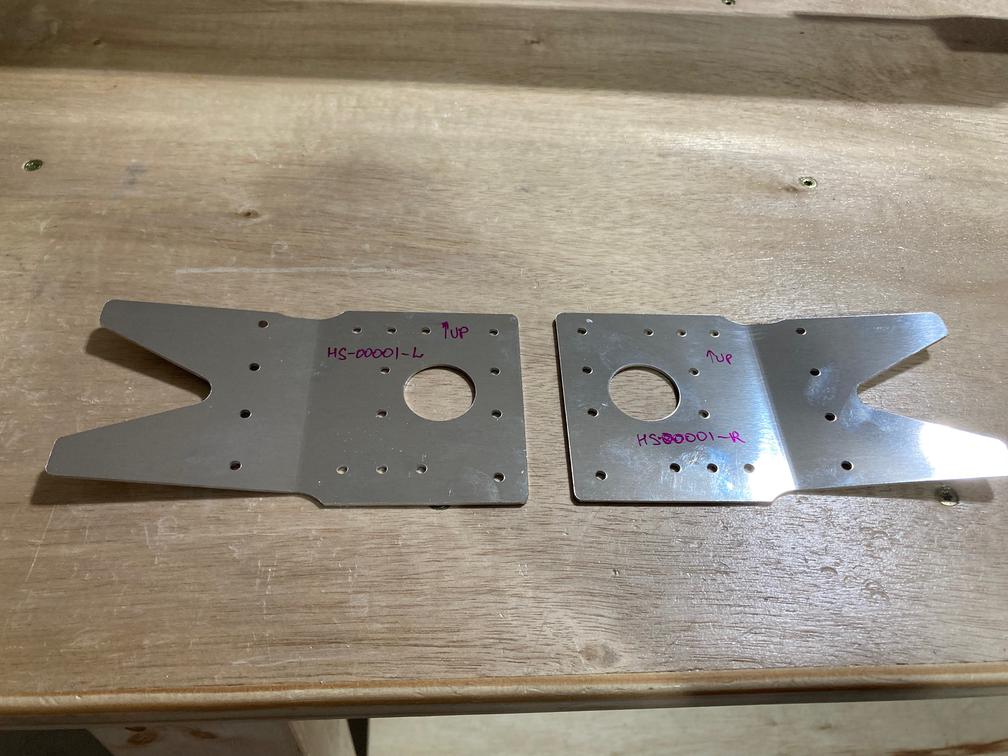
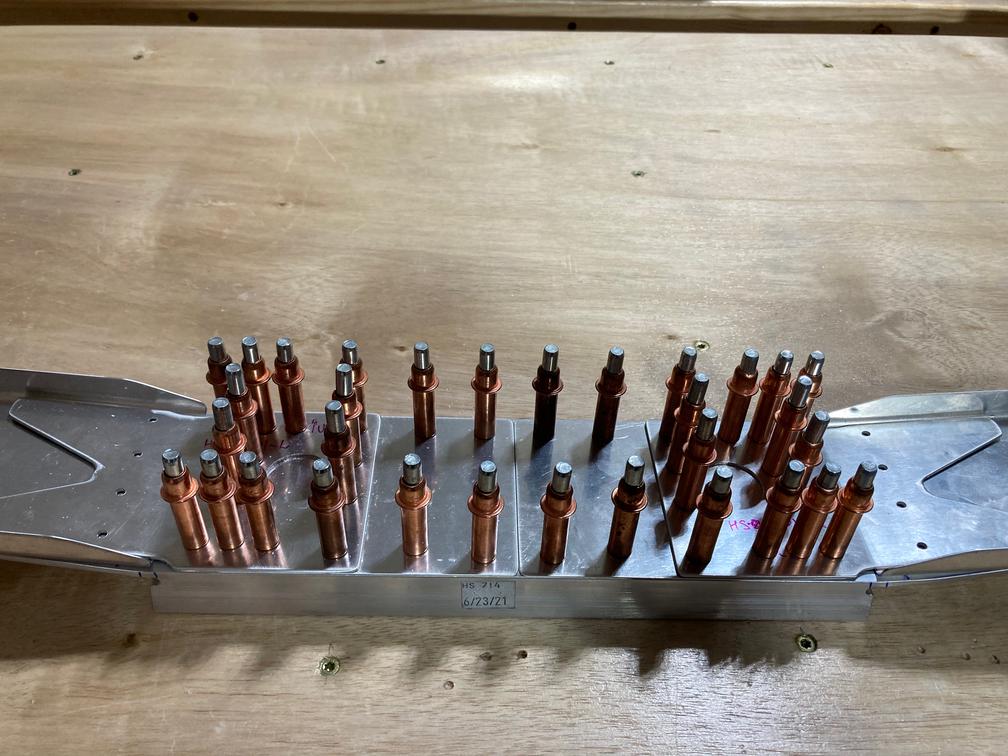
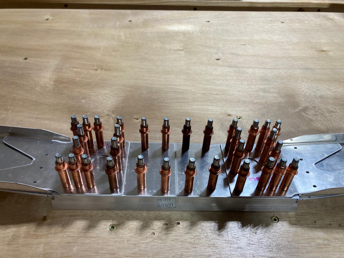
Then after a lot of drilling, the rear spar clecoed together with the hinge brackets.
There was one minor "oops" moment when I drilled #21 holes for the main rib: it did not go exactly as planned. I used my electric drill (to avoid making too much noise), which runs relatively slow (1500 RPM). When I was upsizing holes from #30 to #21, the drill bit grabbed and got stuck in the hole. I tried my bigger electric drill -- the same result, same jagged edges of the hole. Tried my air drill -- well, it got stuck, too. Finally, I was able to drill the holes by using my air drill and advancing it extremely slowly.
This was a bit unexpected -- I am used to that when I machine aluminum I can push a #21 drill bit with not too much drama, on a very low RPM. The difference, though, is when I machine in my mill, the part is clamped and my spindle is more powerful than the hand-held drill. Also, I usually work with 6061-T6 aluminum, which is softer.
In the end, I was able to slowly drill from the opposite side, which worked out okay. The holes look fine.

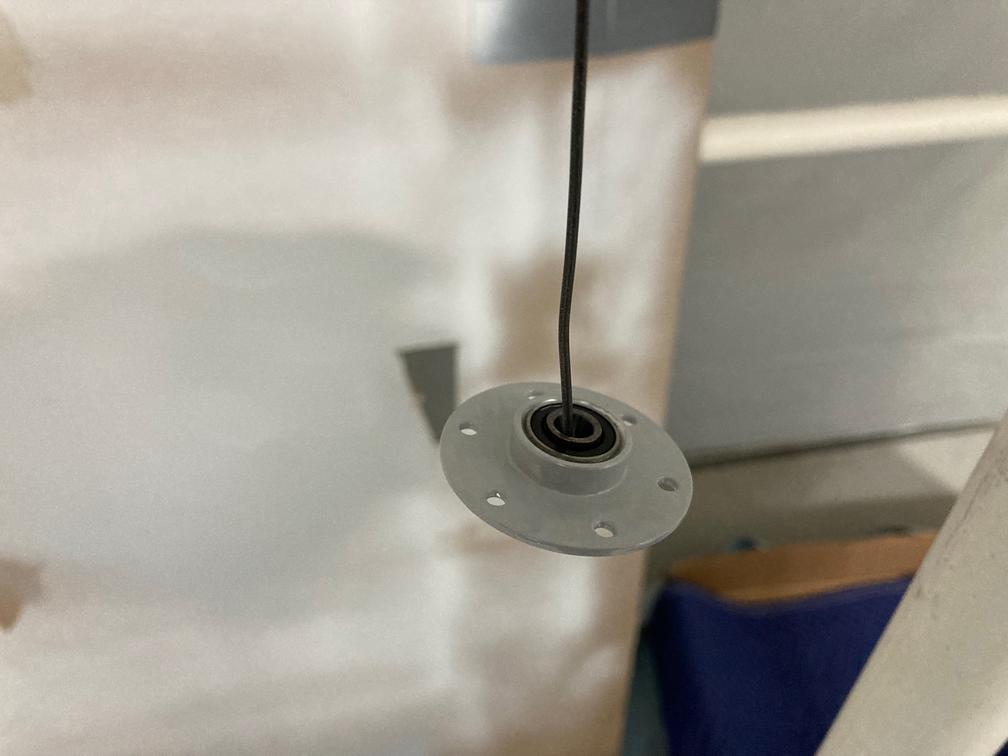
Then I switched to the central bearing assembly. I primed the bearing itself with my epoxy primer, but instead of spraying it, I brushed it with a small paintbrush. It turned out relatively ugly in the end, but it should work. It is going to be hidden between the brackets anyways.
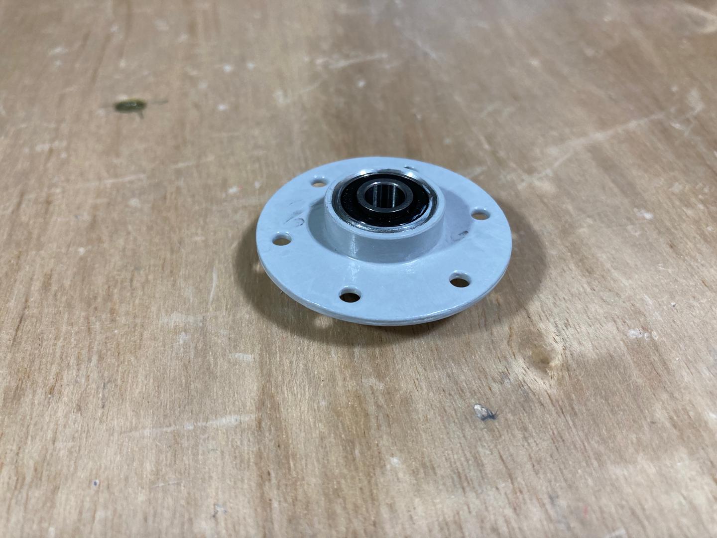
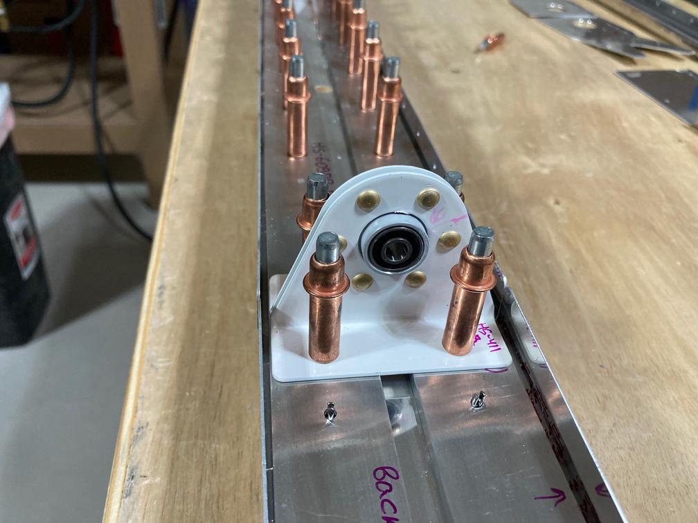
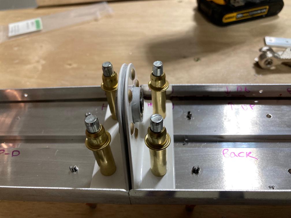
After letting the bearing dry, I assembled it with the brackets.
The instructions specifically called for an AN470AD4-5 rivet which I found rivet to be a tad too short (but again, instructions stressed that -5 is the correct length here). It turned out okay, but heads were definitely on the short side (about 50-60 thou, with 50 thou being the minimum as per MIL Spec.).

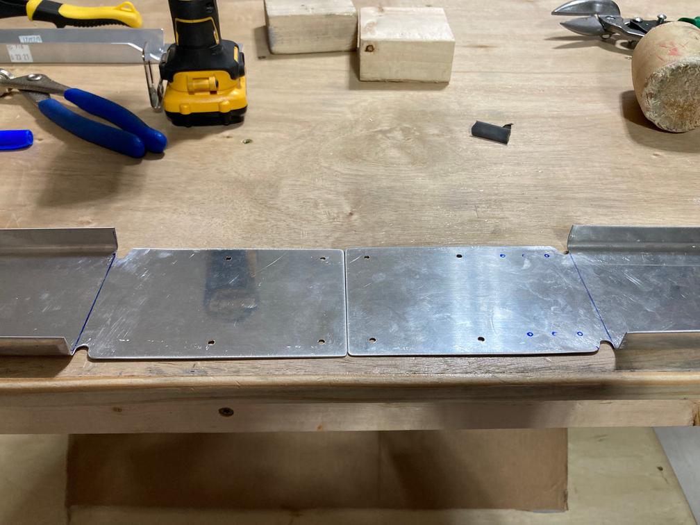
The next part was to assemble the front spar. I started with the doubles, separating them and polishing the edges with the Scotch-Brite wheel. After that, I fabricated (well, rather, modified) the front spar itself.
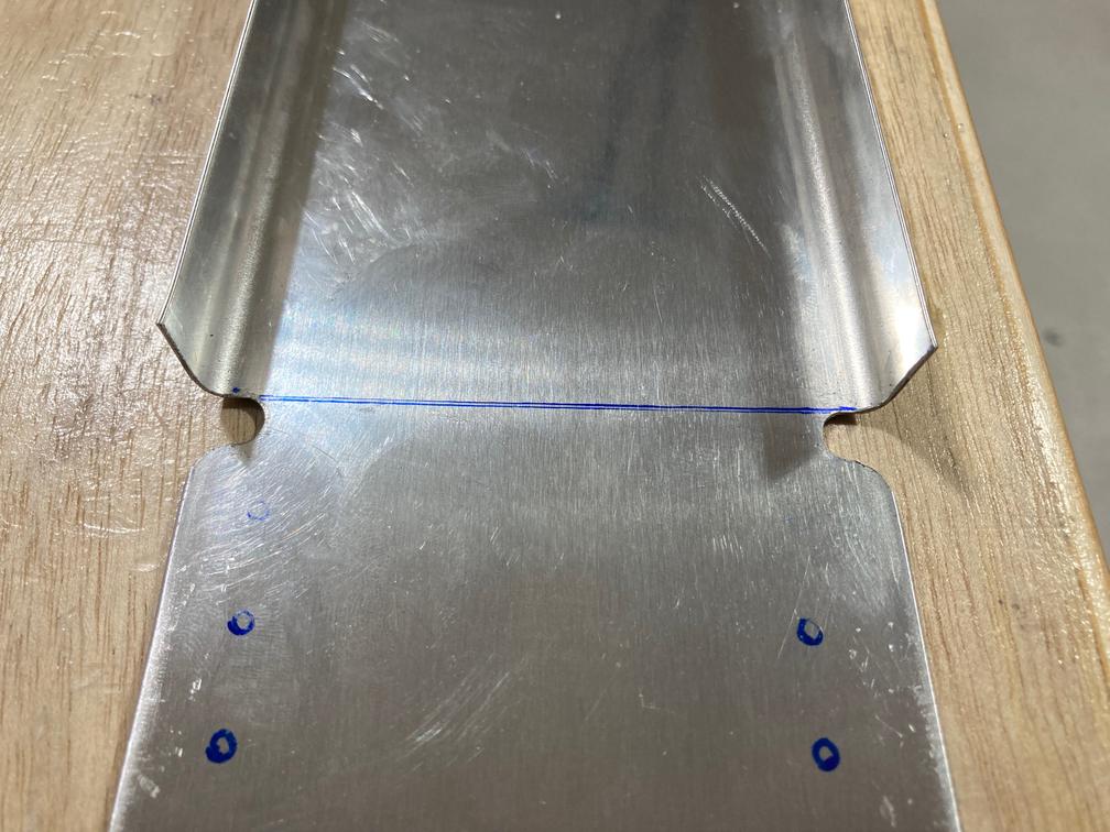
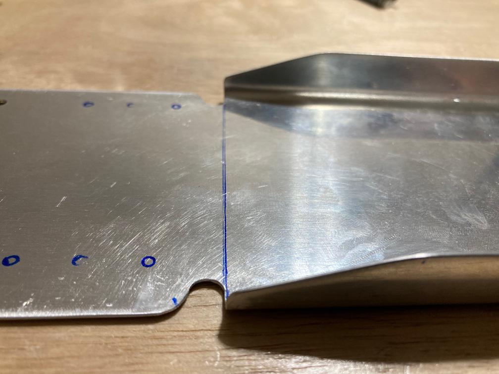
The modification was to shorten flanges and create a relief notch. Shortened flanges need to be flattened back so they provide enough of the edge distance for further drilling. For flattening, I clamped the part in the vise between two aluminum angles (which I use as "soft jaws"). Worked out perfectly.
Then I filed the pieces to get smooth radiuses.


Initially, I thought of leaving flanges square until I know how much I could trim them, as I was intimidated by the note "maintain min. edge distance" on the plans (also, it seems like there are a lot of potential edge distance issues in that area)! However, after giving it some thought, I trimmed them. One thing I noted is that plans say that section F-F is a "3/4 scale", but when I place part against it, it looked more like the actual scale. So I trimmed, hopefully on the conservative side.
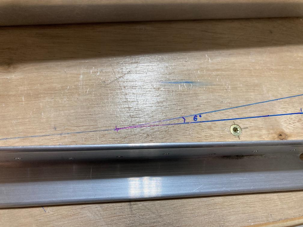
The next step was to bend the front spar and both reinforcing angles. First, I drew a 6˚ angle on the table, so I can measure parts against it. 6˚ turned out to be about 9-9/16" by 1".
Before bending the reinforcement angles, I rounded their corners. This was another scary moment. After rounding corners, I realized that I sanded them just a little. The original edge distance was about 0.25", which is already recommended edge distance for the 0.125" hole. I measured my new distance, and it was 0.222" inches. I checked the MIL Spec and found that the minimum edge for -4 rivet is 0.219", so I am okay (also, I found a similar question on the forum where distance seemed to be even less, and it was presumably okayed by Van's support since the part is so thick).
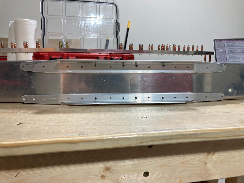
And the final result, after bending and drilling holes inboard of the ribs. I've spent a lot of time meditating on the manual and the plans trying to figure out what exactly they want me to drill (it seemed like two steps were kind of repeating each other). In the end, I decided that instructions were a mix of original instructions plus the service bulletin (the one that adds doublers to the front spar), and that's why it was a bit confusing. Also, it referenced figure 6-6 which I did not find at all (which seems to be a typo).
Also, I disassembled my vertical stabilizer to replace the whole front spar assembly. I asked Van's support if the part could be repaired and they suggested that dressing sharp edges should be enough. However, given that the whole assembly turned out to be not great, I decided it would be better to redo it. Since all holes are pre-punched, new parts should match the skin, more or less.