Creating a trailing edge angle 3h
3h
June 11, 2022
Today I worked on an aluminum angle to hold the trailing edge straight.
One of the key parts of the rudder build is the trailing edge. The trailing edge is formed by two skins and a wedge between them. It is very important to get that edge straight and flat.
The general idea of achieving these goals is to glue it before riveting, so the glue holds parts straight and flat. Two options are offered by the instructions: use VHB tape or a tank sealant.
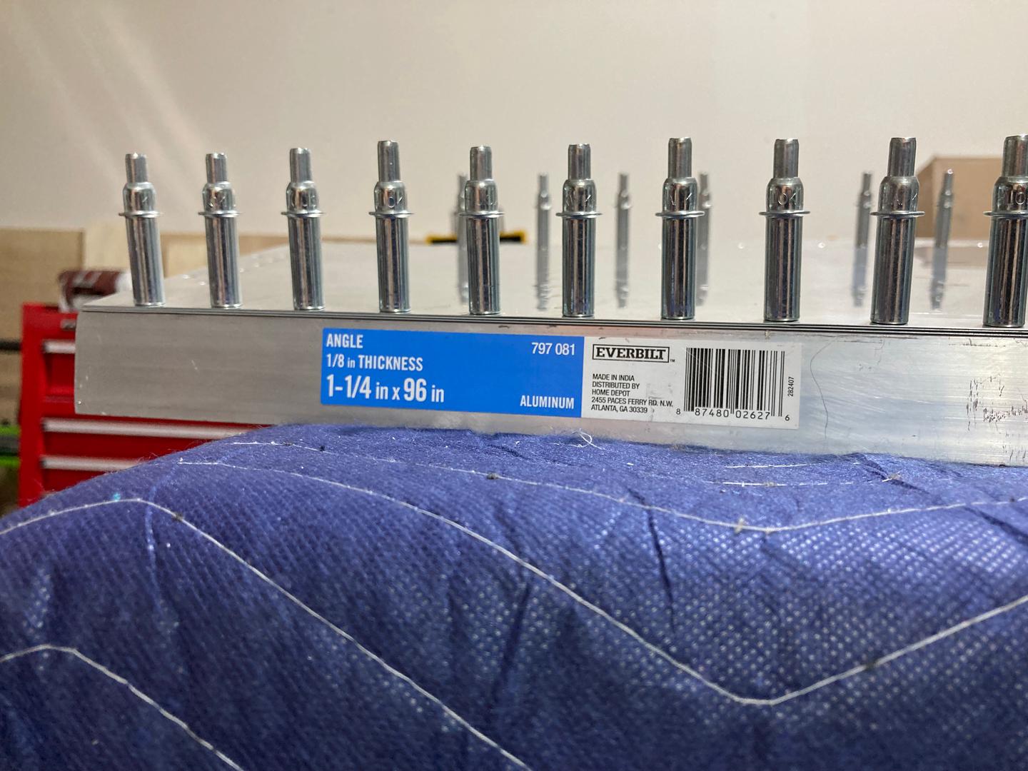
I opted for the tank sealant, for no good reason. For the sealant to work, you need to somehow clamp all the parts together. I decided to use an aluminum angle from Home Depot with holes drilled in it such that it can be clecoed to the parts.
The idea was to use Cleaveland jig to tilt the angle a bit so it matches the half of the angle of the wedge.
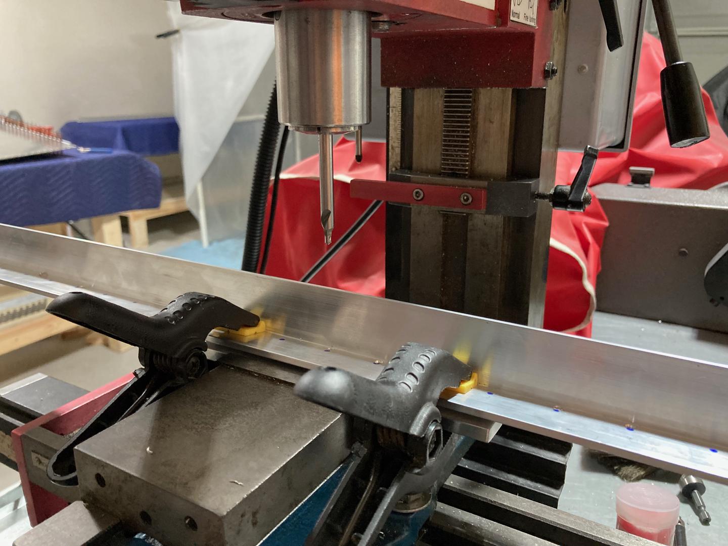
The issue with drilling at an angle is that you cannot use a drill bit: it will wander away. You need to use something rigid to drill. I have a mill, but I did not have a 3/32" end mill, so I decided to use a #3 center drill for that.
A center drill is typically used on a lathe to make "centers" on shafts (which could be then used for mounting these shafts in the lathe), but in hobby shops, they are also commonly used instead of spot drills for starting the holes.
It turns out that the #3 center drill pilot drill is 7/64", which is just a bit larger than 3/32". The silver clecos hold 7/64" relatively well (although, there is not much room for an error), and at the same time, a slightly larger hole allows for some lack of precision in the locations of the holes (you will see later why precision might be lacking a bit). Therefore, it is possible to drill the hole with the center drill alone, without the need to swap the tool for a regular drill bit. Also, I found that my drill chuck has a very big runout for some reason, which is not an issue for the center drill since I can put it into an R8 collet!
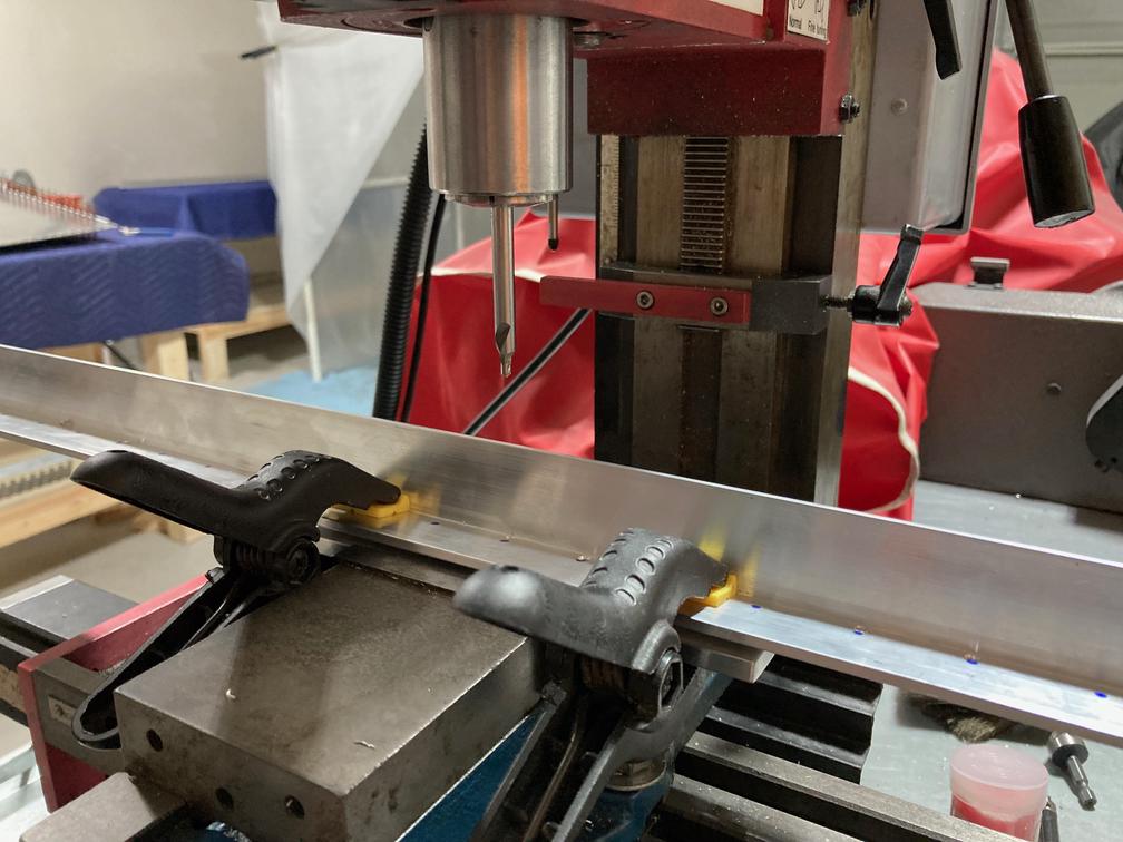
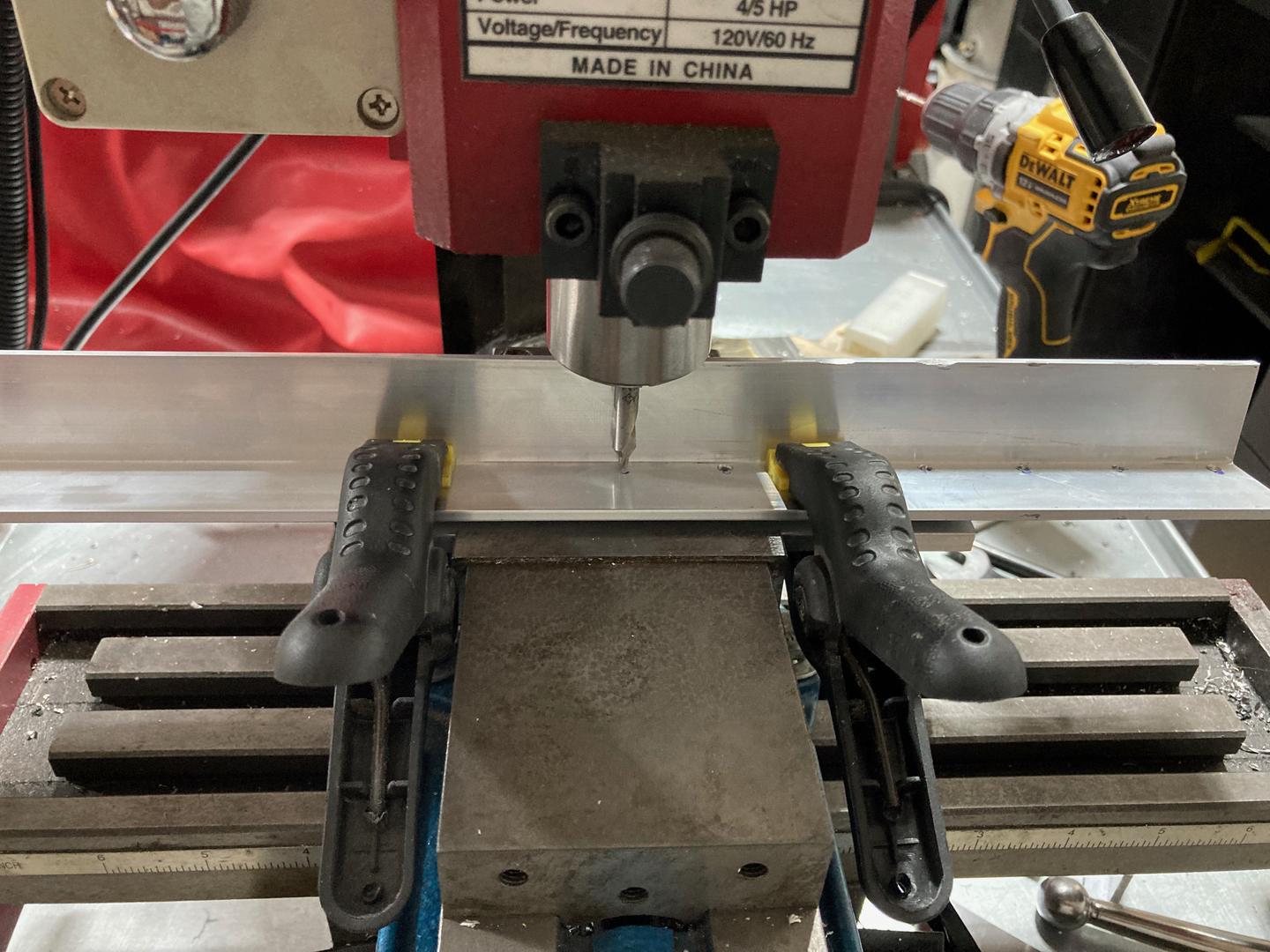
This is what my setup looked like:
I am sure this warrants being expelled from the machinist's school, but hey, I am an amateur A&P, not a machinist!
One minor issue was that the pilot drill was not long enough to allow the hole to be fully drilled. Instead, it would leave a small "bump" on the opposite side which I had to either drill through by following the hole with the real drill bit or by using a counter-sinking tool.
Then I considered different ways of aligning the holes for drilling. One option was to make some sort of a locating pin such that it gives the correct spacing. However, I decided not to do that. The issue with that approach would be that it will accumulate any error in the distance of the pin. 0.001" of an error would accumulate to 0.045" (there are 46 holes, so 45 gaps between them).
Moreover, the spacing between holes is given as 1.062". But what is 1.062"? Is it 1-1/16" ("human" value) that was rounded on a drawing (1-16" would be 1.0625")? Or was it rounded because a CNC machine only has precision up to 0.001"? Or is it actually a metric CNC machine inside, so everything is an approximation?
One option would be to drill through the AEX wedge. However, my wedge is counter-sinked already and I would like to keep it away from rotating cutters as much as possible, just in case. Also, clamping parts together becomes quite important: if the wedge moves in any way, it will ruin the whole process.
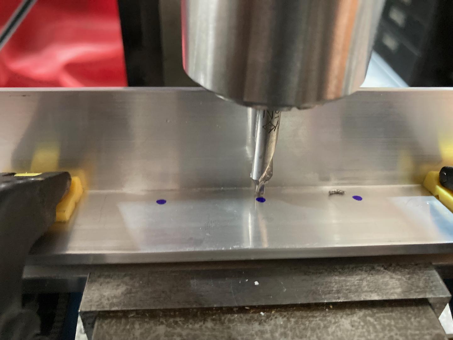
So I went with a very crude approach: I clamped the wedge to the angle and used a Sharpie to mark the location of the holes. Then I would visually align the center drill with the mark to drill the angle. Note that due to the spacing difference only the "X" axis should be aligned, holes would not align on the "Y". The "Y" distance is defined by the position of the drill over the jig (which I did not change for the whole process).
The precision is not amazing, but, generally, you can achieve about 0.005" accuracy just with a naked eye. And the important part here is that this error will not accumulate as all the Sharpie marks are located exactly where the holes are.
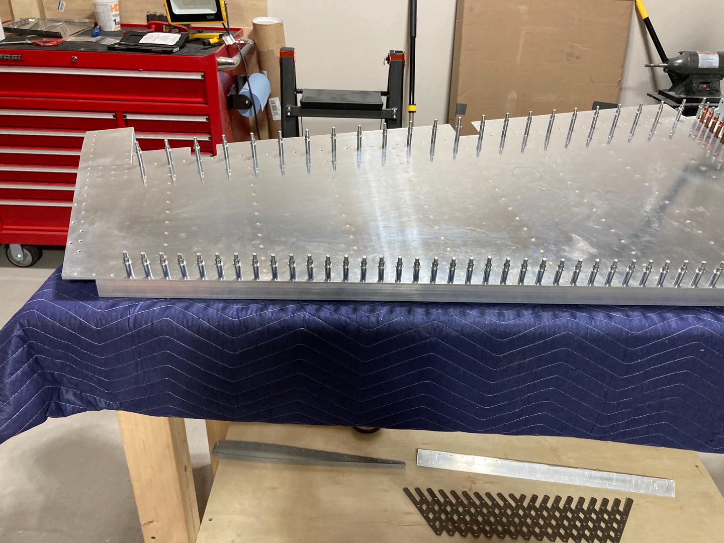
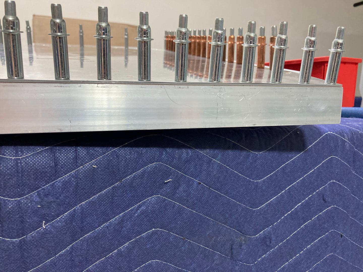
So I drilled all the holes in the angle, and the parts clamped to the angle just fine! Since the center drill is designed to counter-sink, I accidentally counter-sinked a couple of holes which made clecos loose in these holes. Also, the last hole was significantly offset in the "Y" direction because it was hard to clamp the angle to the jig for the last hole (the overhanging part of the angle would lift the angle from the jig). However, other than that, it looked good.
But wait, isn't this angle too short? Did I screw up? Well, I needed a 49" angle, and Home Depot only sold 48" and 96". So I bought 96" and split it into 49" and 47". I used the 47" angle to try my process and figure out the possible issues. Now I need to repeat the same process, but for the 49" angle 😅.
So I did, with a few minor alterations to the process. I used a longer center drill so I can clamp it well in the collet.
For the test angle, I used a deburring tool to "open" the bumps on the opposite side which were left by the center drill. However, since this angle is (presumably) T6061-T6 aluminum, it is very soft and gummy. The deburring tool would leave very ragged edges and require some sanding. For the real angle, I went with the wood chisel to cut these bumps off. Put a flat side against the angle, position it against the bump, hit with the hammer and the bump is cut off (would they expel me from the woodworker school, too?).
Well, anyway, it worked well and left a pretty flat surface. It only needed just some very minor sanding.
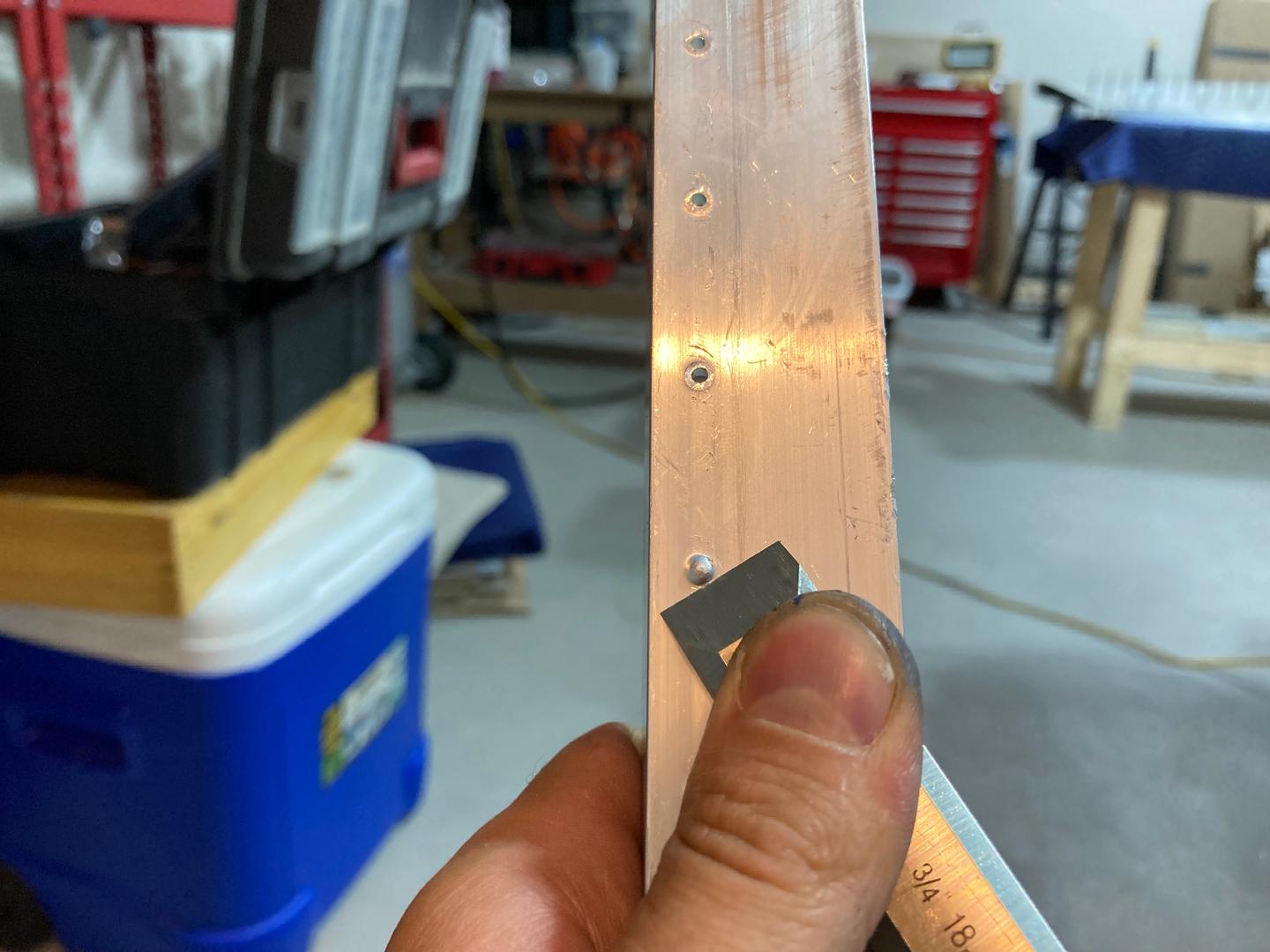
The end product was pretty accurate, every hole aligned with the trailing edge just fine.
I think, if I can glue it together just like that, the final edge should be good enough.
Meanwhile, I am thinking how am I supposed to rivet the trailing rivets in the bottom rib. There is not much space here, and these rivets now use -4 rivets (after my previous mistake when I had to open all the holes for the -4 rivets) which requires more force than -3 rivets.
Currently, I am considering an approach suggested in the practice kit: making a flat bucking bar and using an indirect riveting technique. For the practice kit, I used some scrap which still I have, but it is too short for -4 rivet (it was very springy even for -3, but -3 is relatively easy to set, so it worked out).
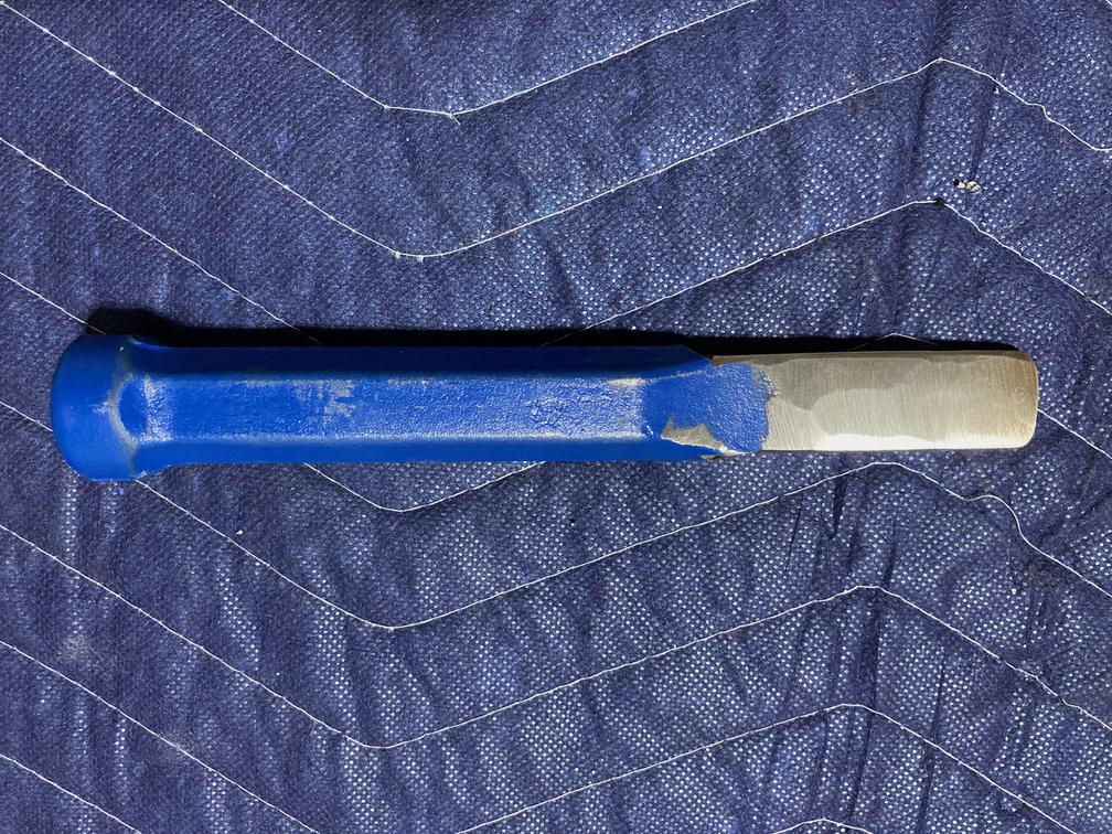
My solution was to form a masonry chisel into a bucking bar. I assume that they should be resilient to hammering since they are used for that, they are relatively heavy and strong. Will see how it is going to work out.
I don't have the image of the chisel in its original form, but after cutting one unused side of it, it looked like this:
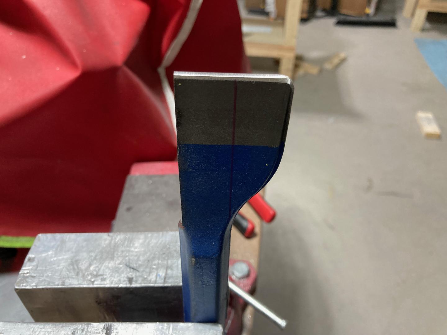
Then I cut the second half and it now looks like this:

I need to sand it a bit to remove sharp edges and test it on my practice kit.