Riveting the rudder skin 5h
5h
June 13, 2022
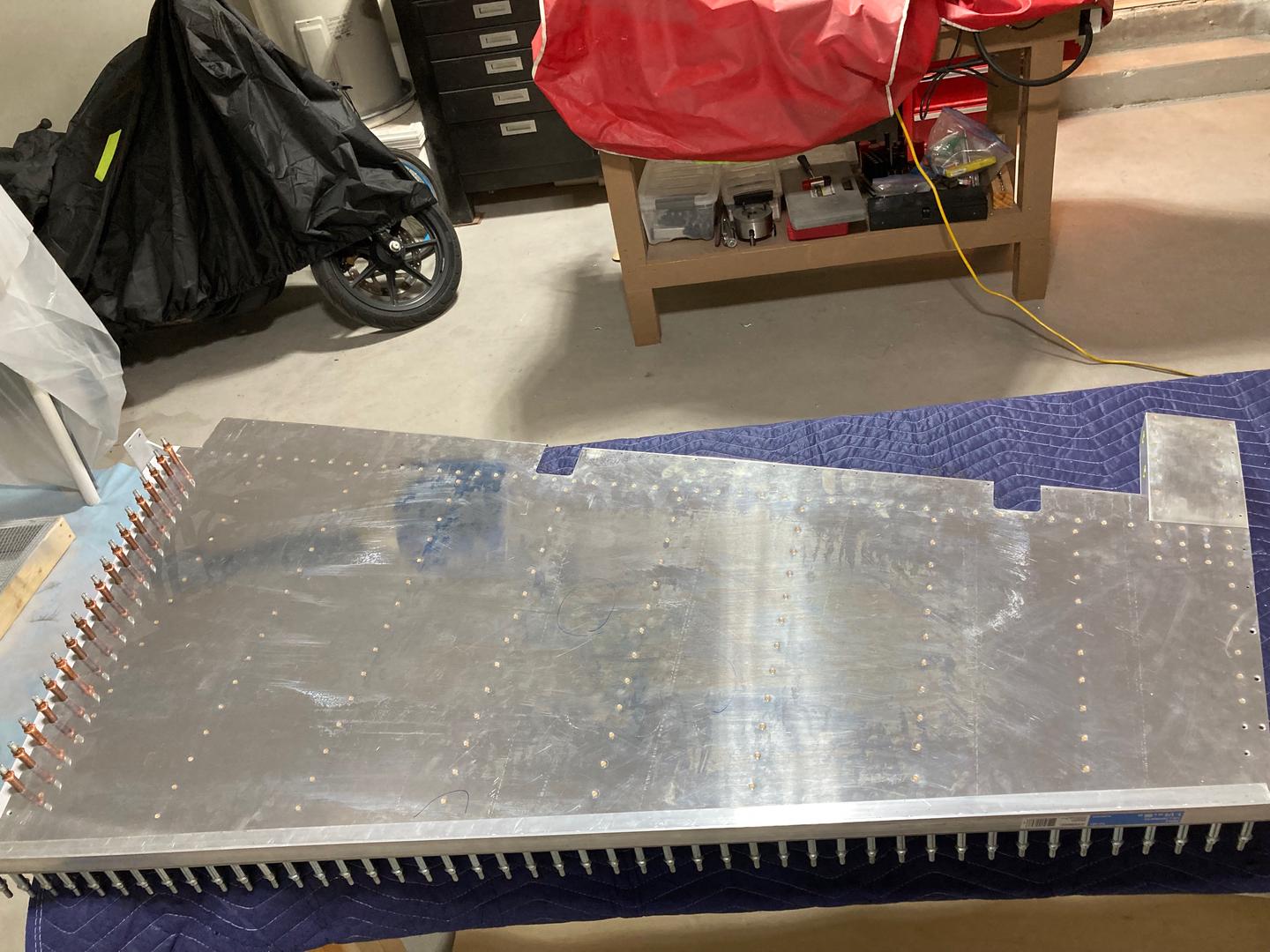
Today I started riveting the rudder skin to the skeleton.
I started with riveting the leading edge to the spar. Nothing too special, used both of my squeezers to set the rivets. I found that even when mass squeezing rivets I have a preference for the manual one as it allows control of the squeezing process. Sometimes rivet starts to lean for whatever reason (possibly because dimples are not perfectly aligned?), and with the manual squeezer, it is easier to catch that.
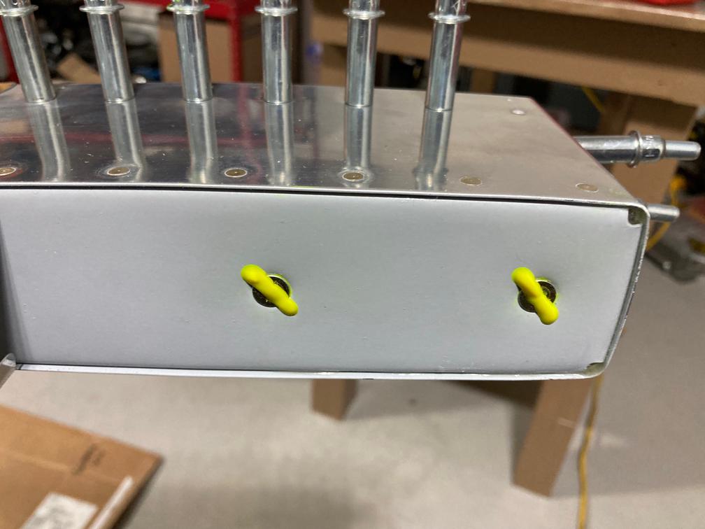
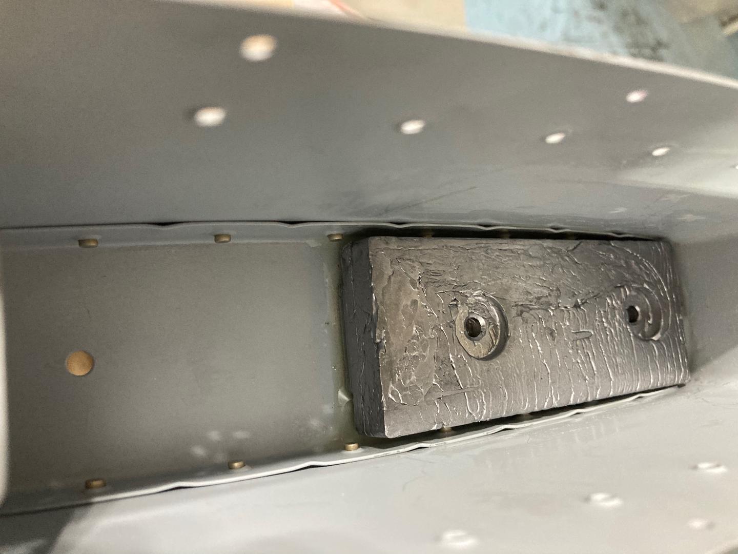
Then was the time to install the top rib. However, before that, I needed to install the rudder counterweight. Per the manual, it needs to be attached with two screws and the nutplate strip with two nut plates.
Since this assembly will be completely inaccessible once the rudder is riveted together, I wanted to glue the counterbalance in its place. One option suggested on the VAF is to use tank sealant, which is what I planned initially.
However, after giving it some thought I decided to go with the T-88 structural epoxy instead (which I bought for the trailing edge, but now I am considering using tank sealant for it!). I was expecting epoxy to encase the lead, permanently locking it in place.
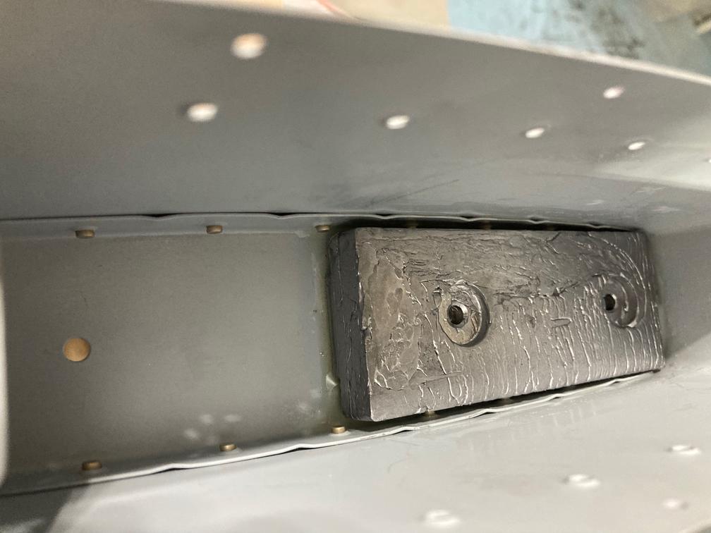
So I mixed the epoxy and glued the counterweight in.
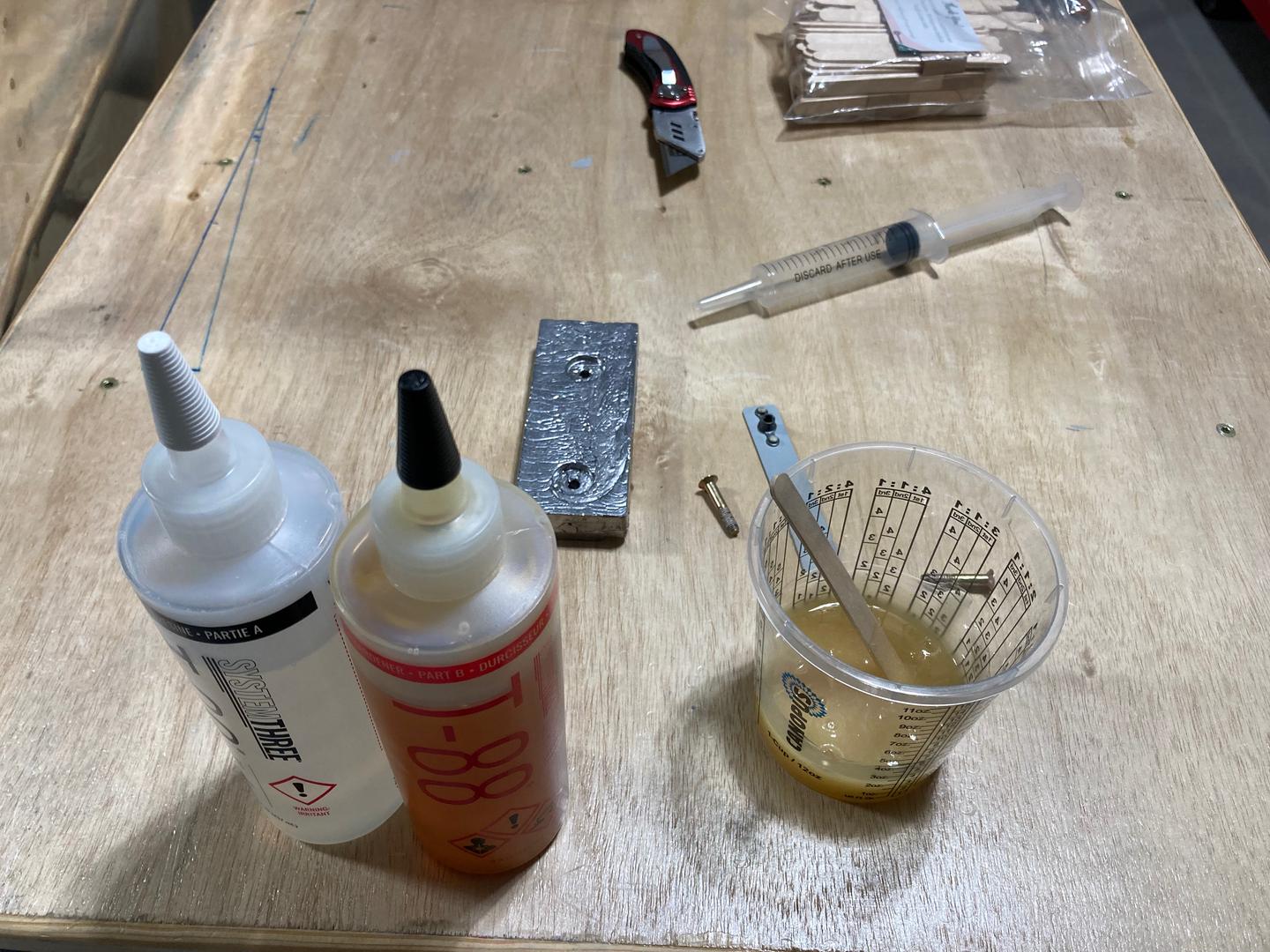
What I did not realize is that this epoxy is quite thin, so it was leaking out. Oh well. Should have tried it on something else first, I guess. I still got enough epoxy under the weight to keep it attached.
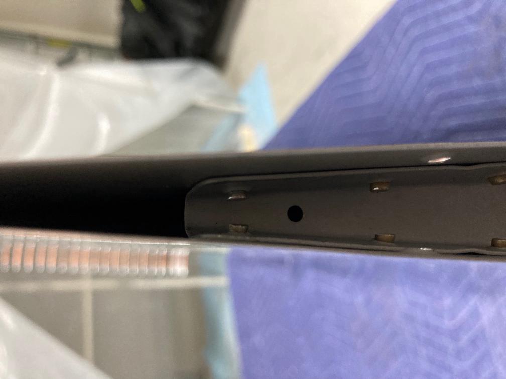
When I put the screws in, I tried to torque them to the specification. For the #10 bolt, the torque should be 20-25 lbfin (pound-inches), plus the friction of the nut plate. I estimated the friction to be less than 5 lbfin, so I put 25 lbf*in on my torque screwdriver, so I get into the proper range.
However, while torquing, the nutplate strip started to bend. The issue is that there is no support behind the nut plates. The original design used nuts, so the counterbalance has two counterbores for them. However, if those nuts become loose, there was no way to torque them back. So, the design was changed to use the nut plate strip, but the counterbalance still uses the same mold.

I was considering keeping it like that, but it bugged me. It does not look right and also if anybody decides to torque these screws to the specification down the road, it will risk breaking the nut plate strip. This is exactly what happened when I tried to torque it a bit more -- the strip got some cracks.
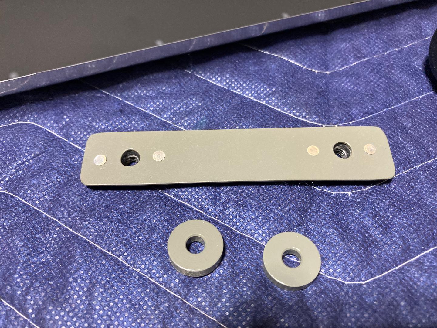
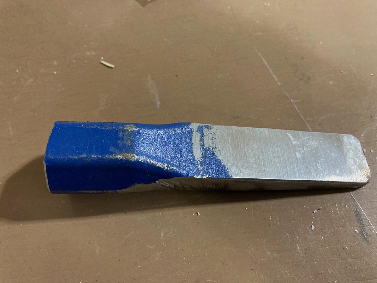
So, I decided to rebuild this part from trim stock and put two bushings behind the plate to provide support for it.
Luckily, I have a small lathe and some aluminum stock.
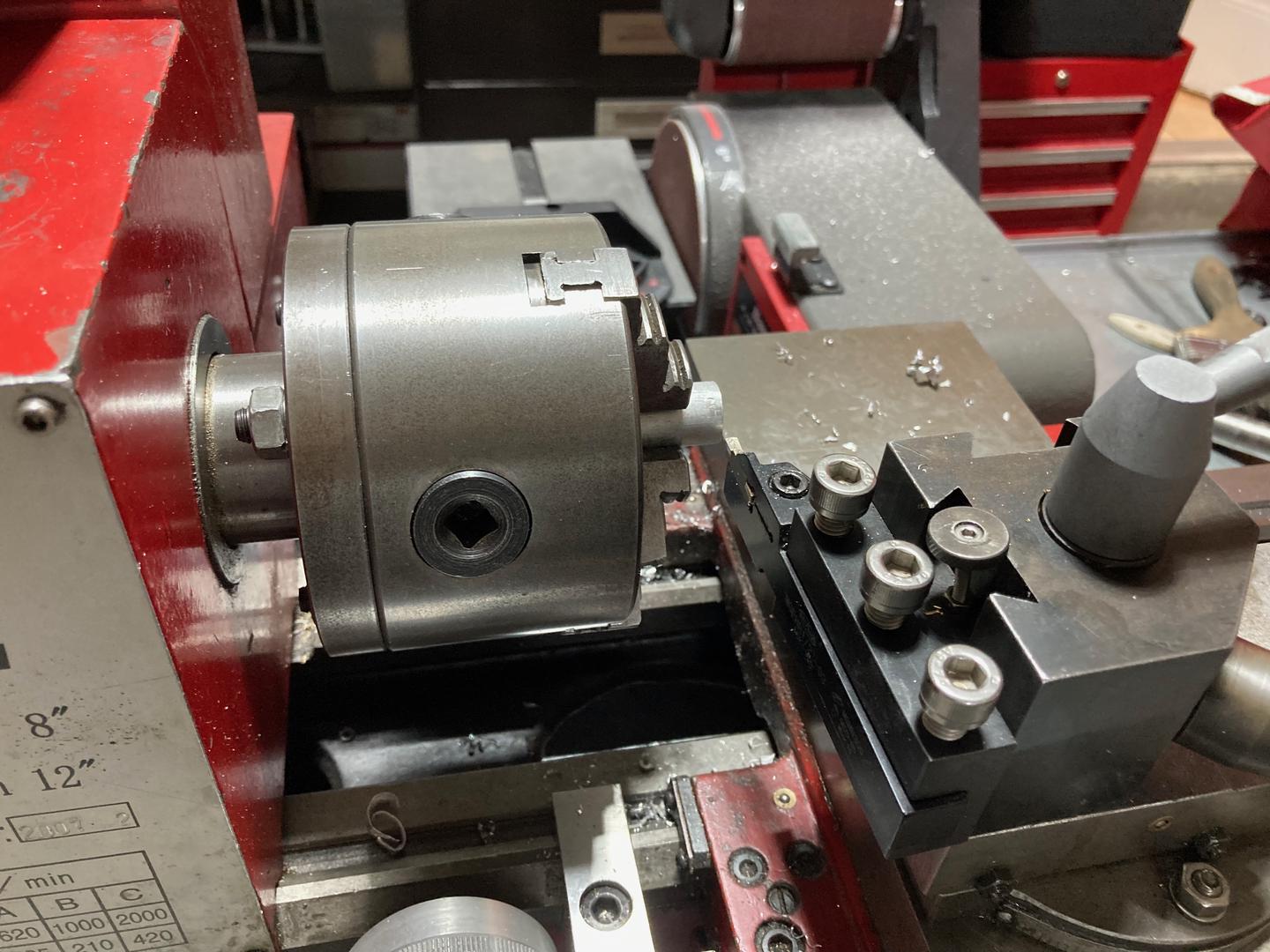
Half an hour later and I have a new strip and two bushings. I primed them with SEM EzCoat. This is what I experimented with when I built my light box, it was on my short list of primers (but I decided to go with the EkoPoxy instead). It is pretty tough and dries very fast, the only two disadvantages are that it smells (since it is solvent-based) and is also too expensive for large parts. However, for small parts, it works extremely well.
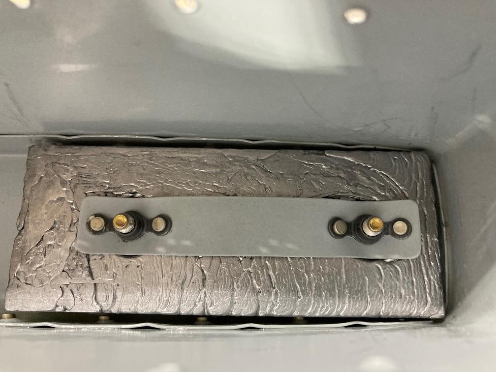
You can see that I was not very patient when I did the strip: one hole is tri-lobed and nutplate attachment rivets are not perfectly centered. Nobody is going to see that part, though, so who cares.
The installed parts look good. Nut plates are a bit scratched, later I realized that maybe I should have added some protection to them. Too late now.
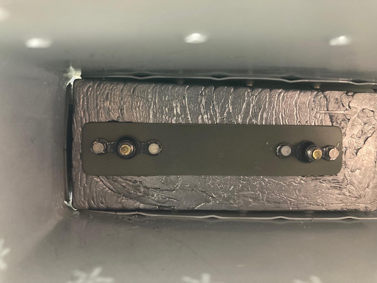
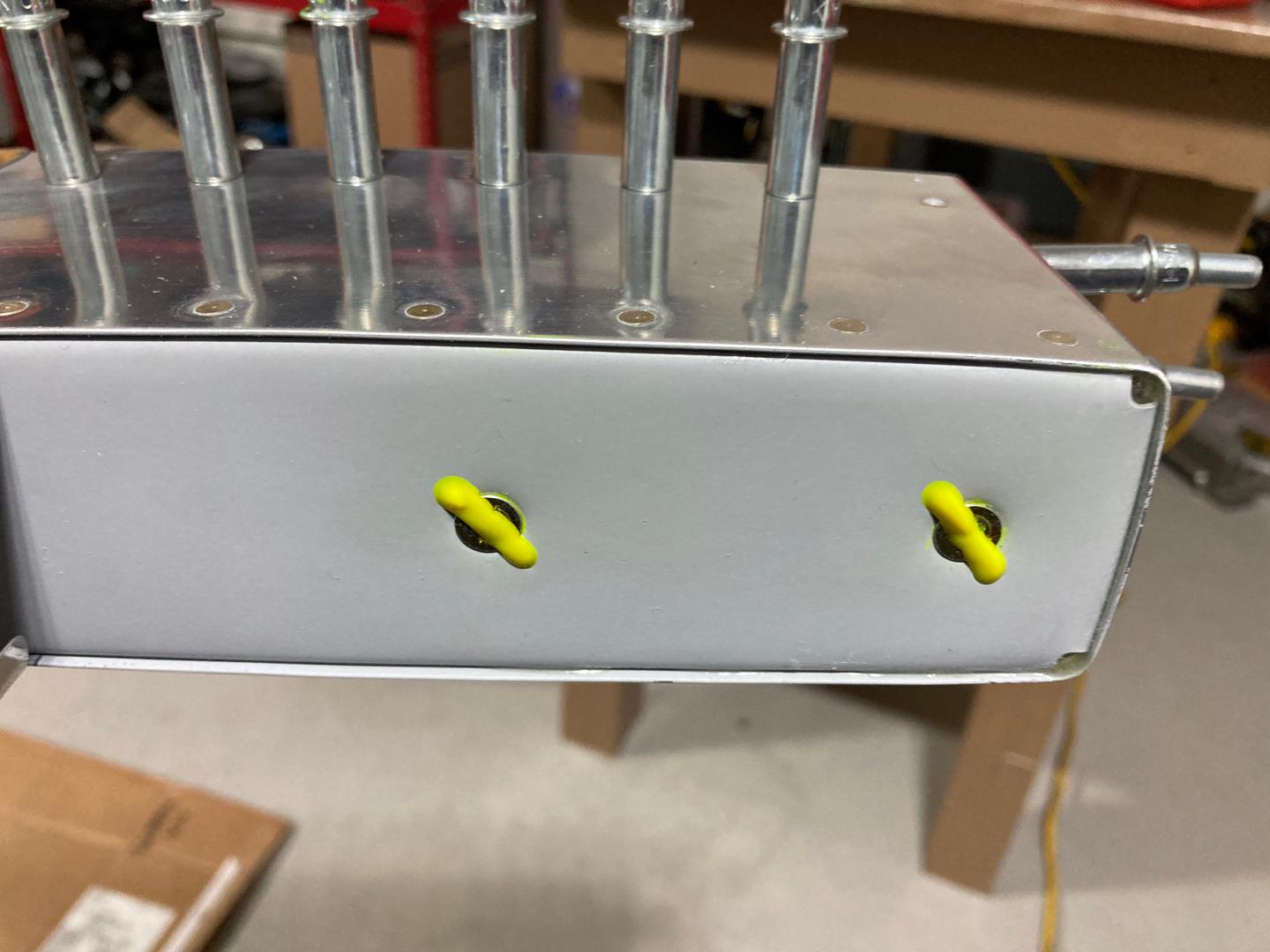
The best part was that I was actually able to get that "click" from my torque screwdriver! Very satisfying. I marked the parts as torqued.
After the counter-balance was installed, it was time to rivet the top rib. Most of the rivets on the rib flanges were easy to set, but I had an issue with one side. For some reason, all rivets on one side would cleat to the side. I think this was happening because the skin was a tiny bit offset relative to the rib. I had to drill out a couple of rivets out to start over.
I did a few things to make sure they were set straight. First, I switched to the manual squeezer as it allows me to see what is going on. Second, I pre-squeezed rivets just a tiny bit to make them a bit fatter (but such that they still fit in the dimpled hole). Finally, I used other tools to shift skin just a tiny bit to get the first couple of rivets straight. After the first rivets, everything went well.

Then I got to the last two rivets on the ribs. The space is very limited around these rivets, so the plan I had was to use indirect riveting with the custom bucking bar I made. I modified the bar slightly (pretty much, cut it in half) to make it easier to use (it has issues with balance/fulcrum).
I was able to set second to the last rivets using this bar. The procedure was to place the bar on the rivet shop head and hit the bar with the hammer. The alternative is to use a rivet gun, but you need to hit it hard and I find it difficult to control a 3X gun with high pressure. Much easier to hit hard with the hammer (but better not to accidentally hit that rudder!).
The last two rivets are going to be even more pain. I can fit the bar over one rivet, but once I set it, there won't be much space for the other rivet. Will see, maybe, I can spread rib a bit.
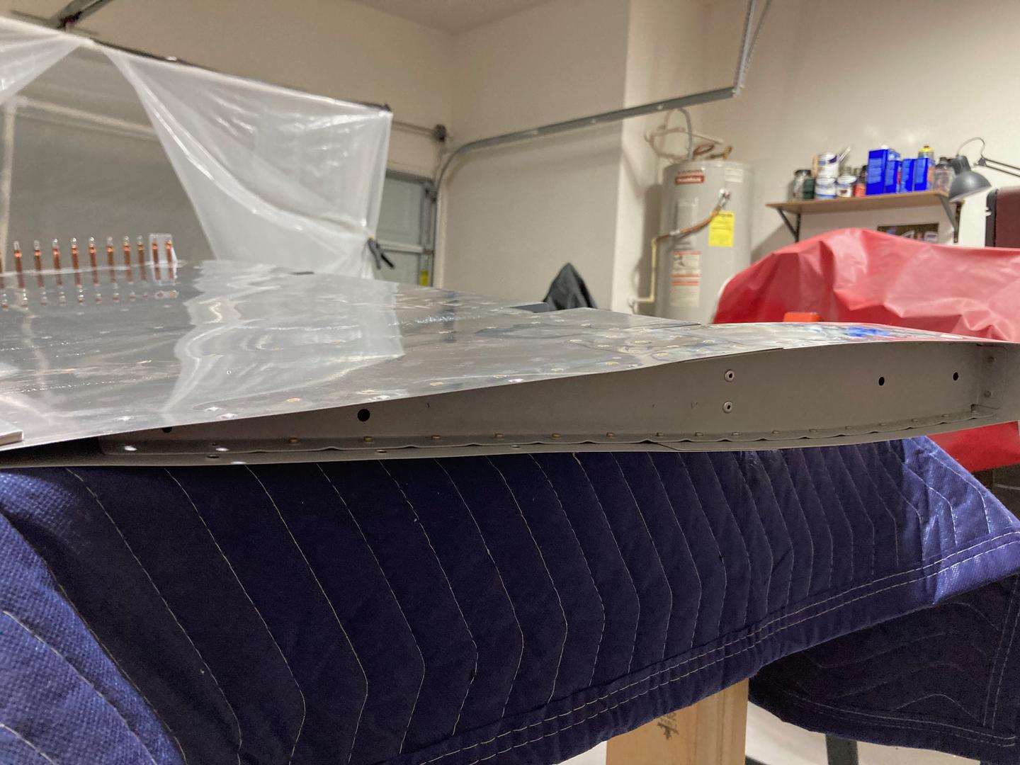
The rudder is partially riveted (I am still waiting for the rivets for the bottom rib, I did not have the correct size).
The next day small update: with my custom bucking bar I was able to set the for trailing rivets. They don't look amazing, but they are swelled enough to hold the skin.