Finishing the service bulletin SB-00036 5h
5h
August 24, 2023
Today I assembled the flaps actuator support channel, finished the service bulletin, and drilled the elevator's hinge point.
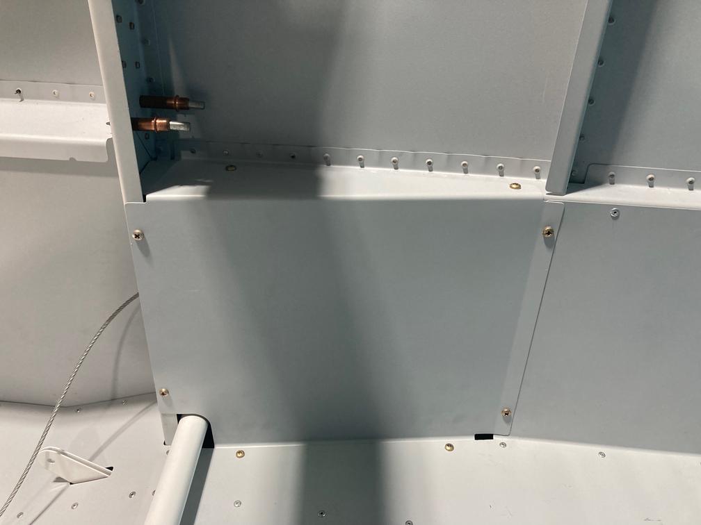
The first thing I did I install the side covers, just so I don't have them lost somewhere. I won't be doing flaps links any time soon, so the covers are fine.
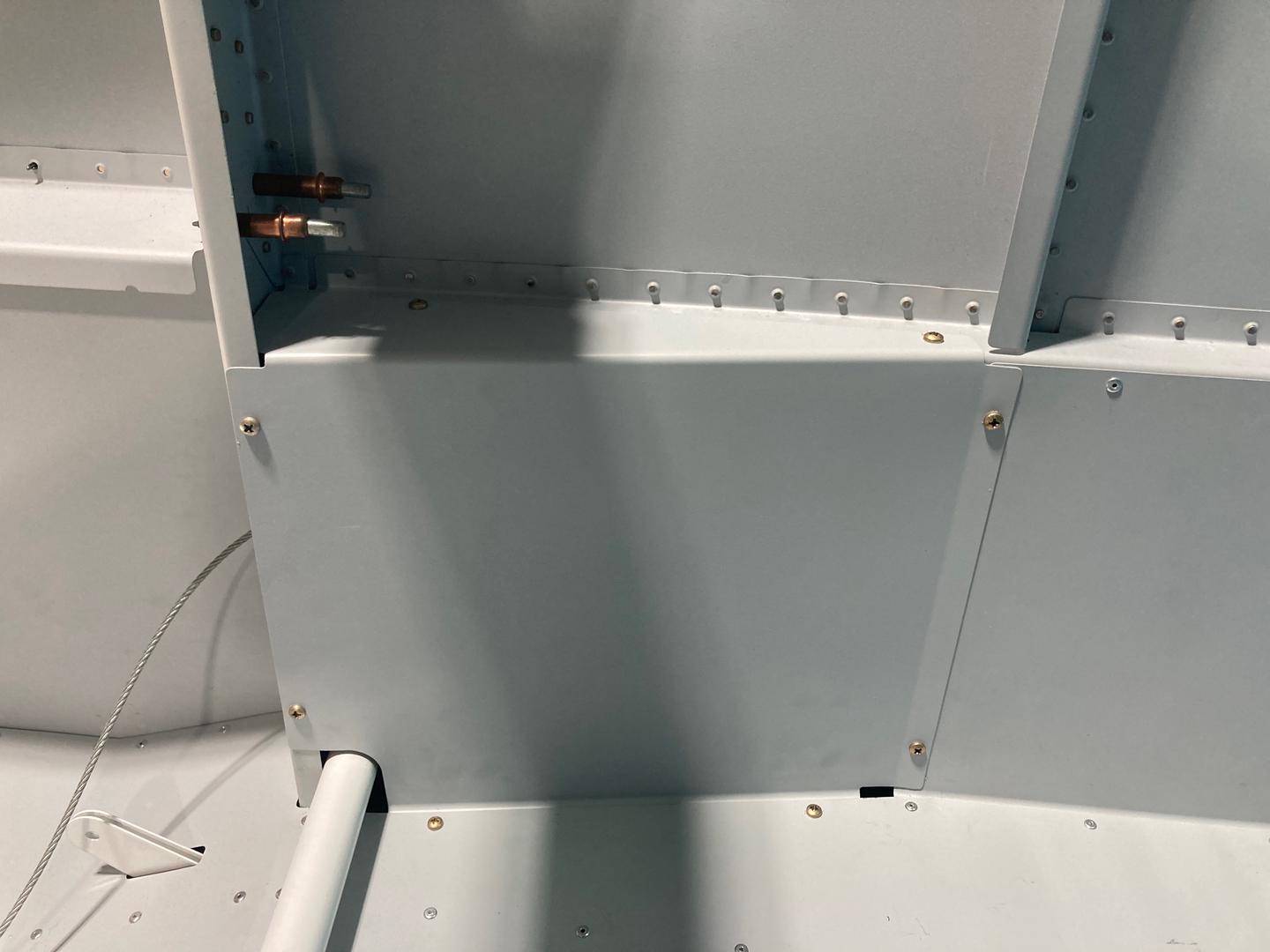
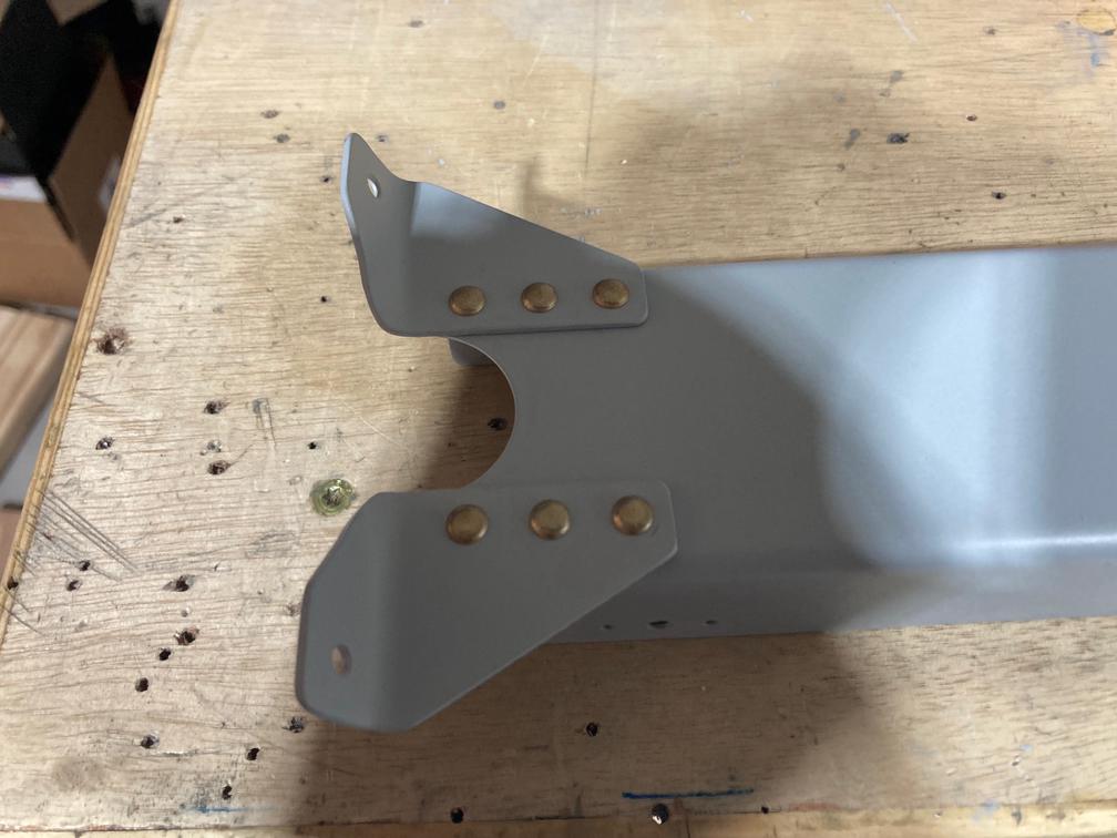
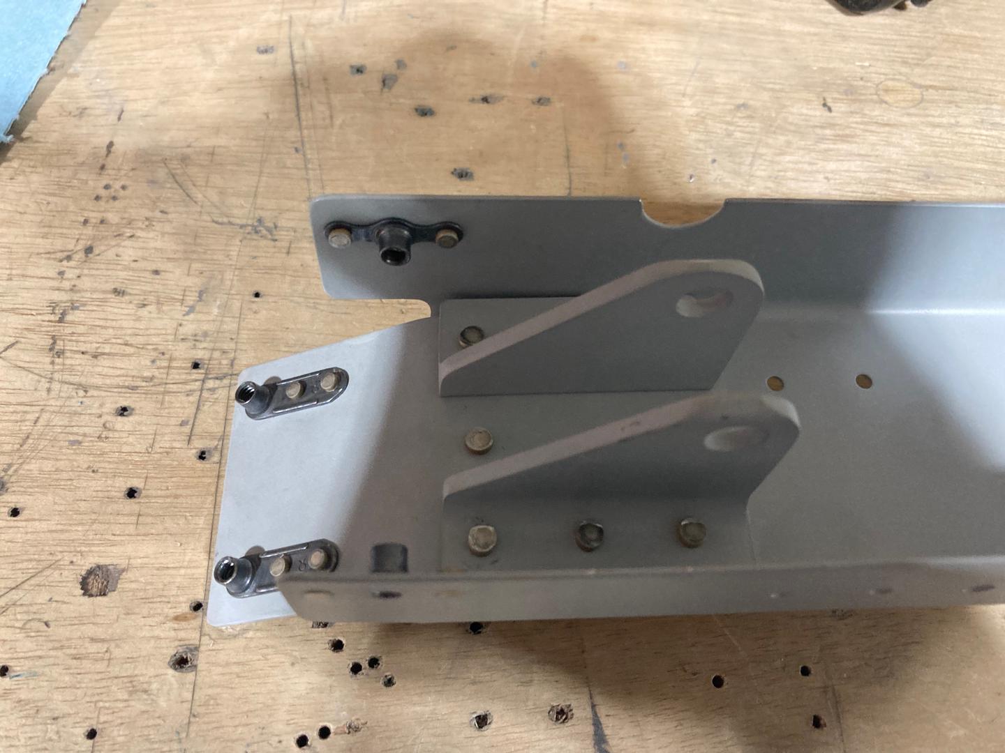
Then I assembled the flaps actuator channel. The two F-758 bottom brackets are installed as per plans.

However, the top part of the channel is a deviation from the plans as I am installing an RV Max Flaps actuator. The way I installed it is I made a custom F-767 attach plate. It is longer than in the plans and acts as a spacer for the support angles. The support angles I got in a retrofit kit together with the RV Max Flaps actuator.
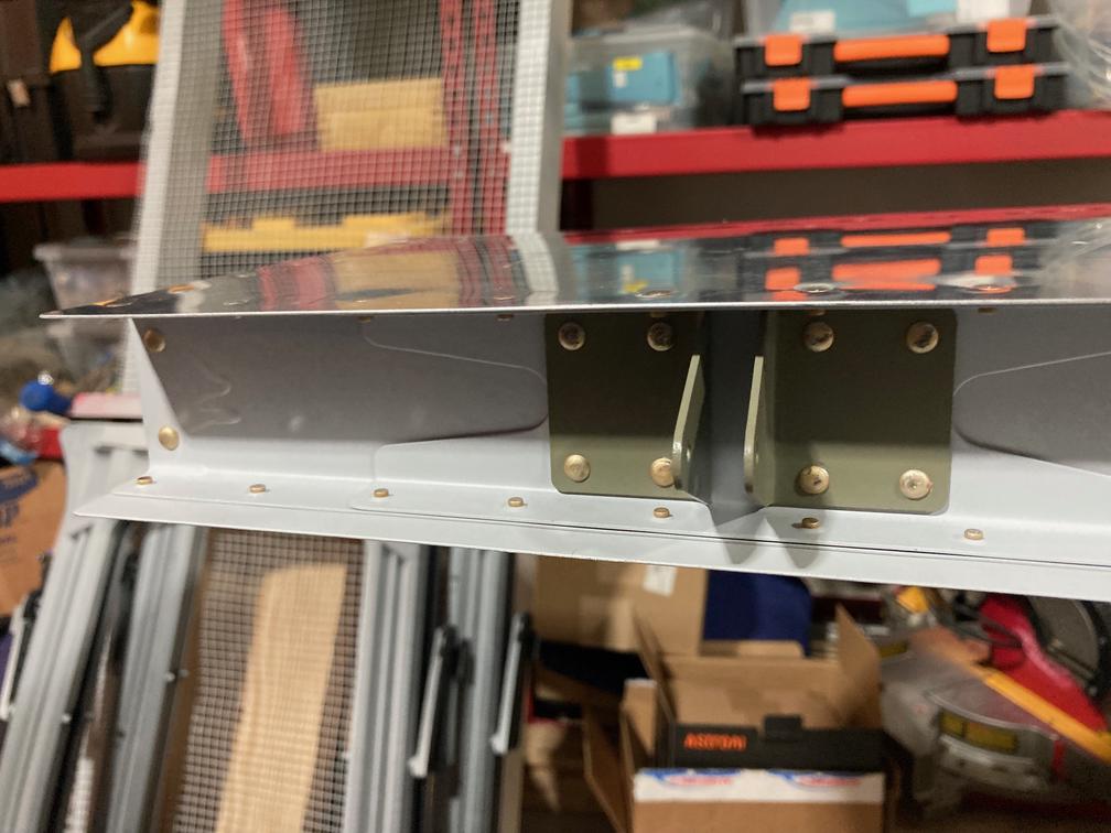
The mechanism assembled.
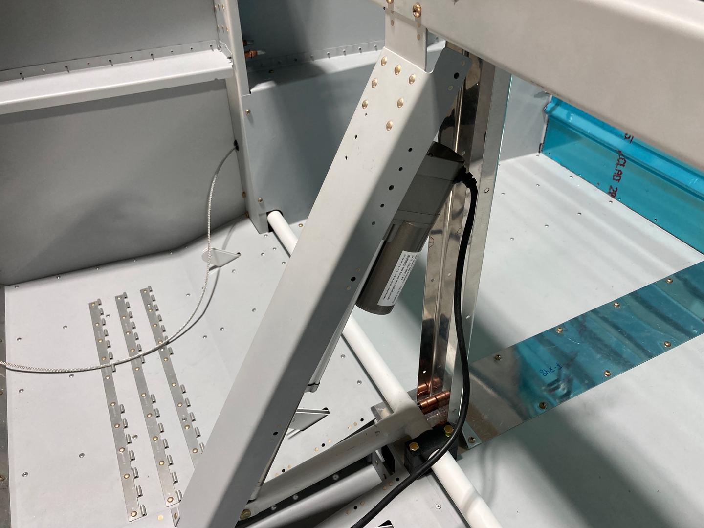
I will have to watch for the electrical wires, it seems like there might be some interference with the nut plate for side covers.
Then I finished the SB-00036 service bulletin. Since I drilled enough rivets to fit my hand and the bucking bar in, I used solid rivets. For the "bottom" rivets (actually, they are the top rivets as the stabilizer is upside down), I simply put the bar on the skin and held it such that it is perpendicular to the shop head.
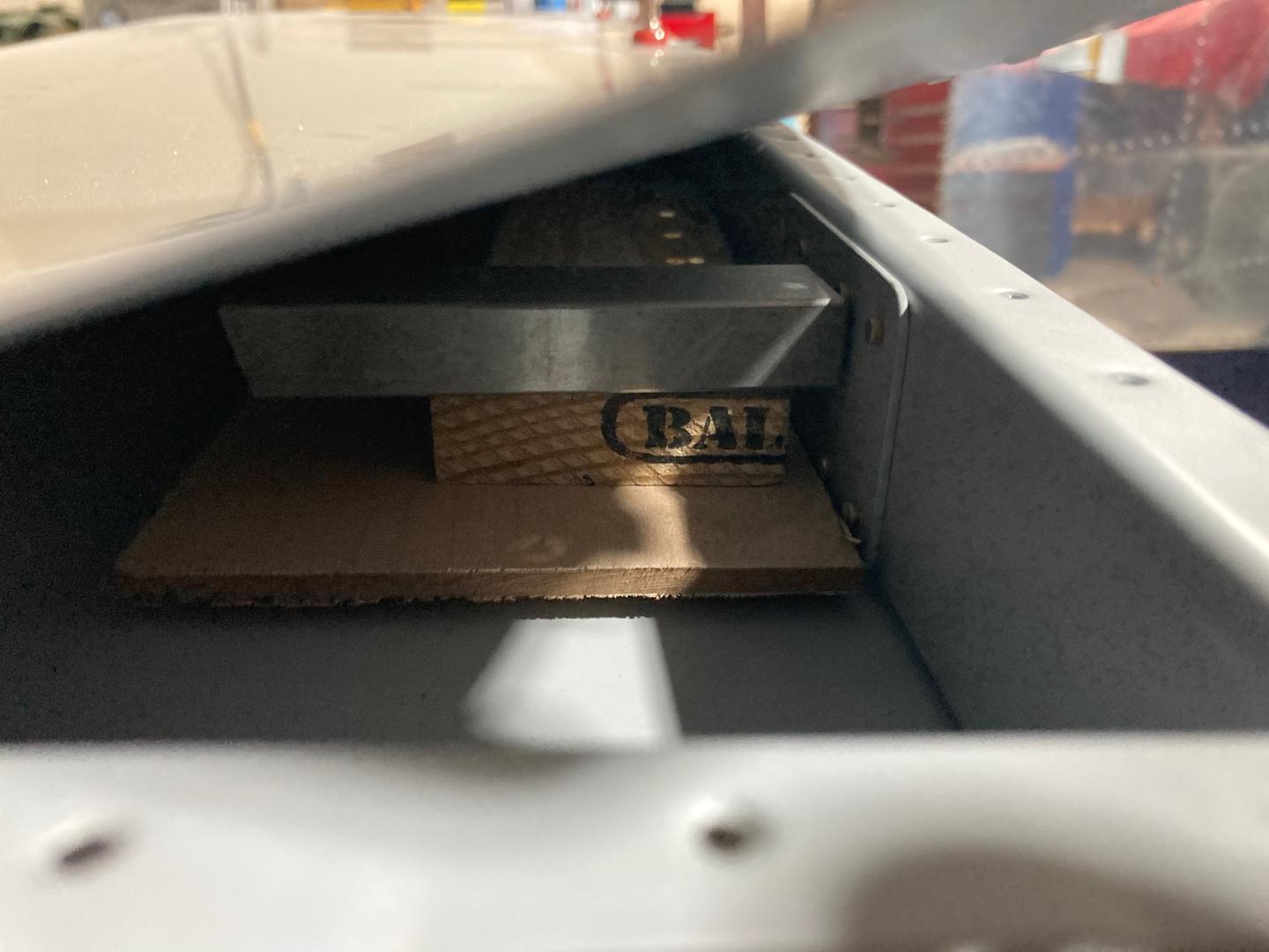
For the "top" rivets (bottom), I used wooden blocks to raise the bucking bar to the right height so I didn't have to hold it in my hand. Then, the procedure was the same: just keep it straight.
The riveted doubler.
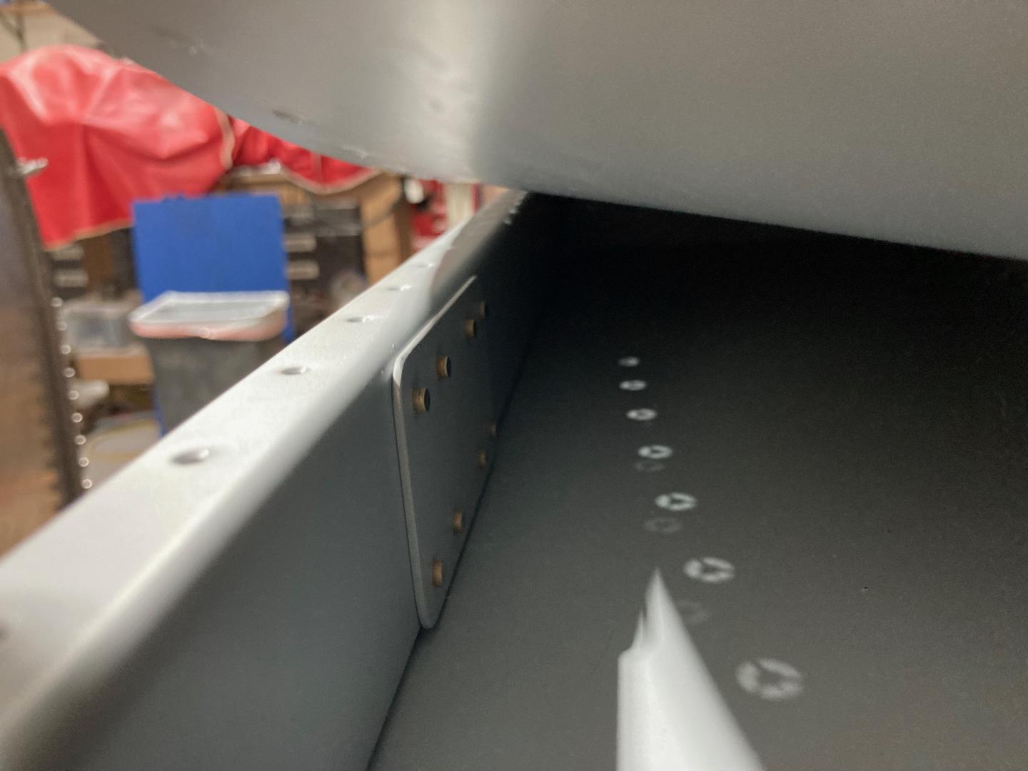
The finished result of the SB-00036 service bulletin.

After that, I tried the elevators. Since I did not drill the central hinge point when I built them, I needed to drill it now.
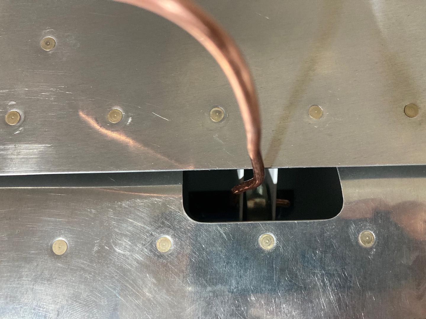
First, I created a "tool" from a copper wire to help me align the elevators (or, rather, just hold the elevators at the hinge point).
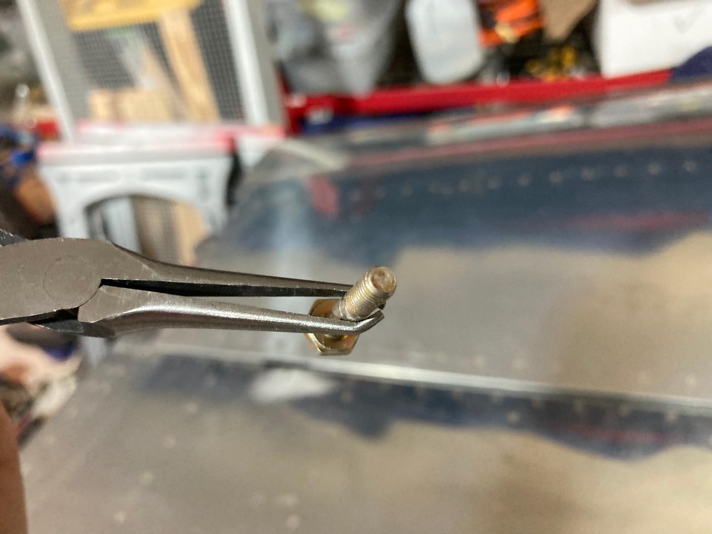
Also, I modified pliers to help me hold the bolt while I insert it.
With that, I followed the plans and drilled the hinge point. I used my brass tubes as bushings to drill the hole, using the central bearing as a guide.
I removed the elevators and upsized the holes to the final side. When I put them back, I realized that the hole was a bit too close to the tube! This is apparently a common issue, and I knew about it, but just forgot!
In my case, the hole is far enough that I can tighten the nut (but only on one side, on the other side the distance is a tad smaller). This requires some slight filing of the nut. Also, I had to file a washer under the nut a bit, due to the welding bead around the tube.
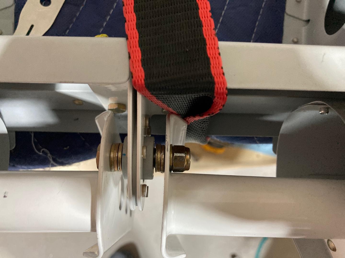
I think it's all good. There are also smaller bolts (NAS623-2-?), nuts (MS21042-4), and washers (NAS620-10) that could be used, as per Vans Airforce Forum which could be used as well. I think, I will go with the standard hardware, as I only did very little modification (the nut would probably turn just fine if not for the powder coating).