Repairing the vertical stabilizer fairing 3h
3h
September 21, 2023
A little setback on my vertical stabilizer fairing and some progress on the bottom rudder fairing.
After some persuasion, I was able to remove the tail beacon from the vertical stabilizer fairing. Took a bit of work, though. The epoxy stuck to the scotch tape pretty well.
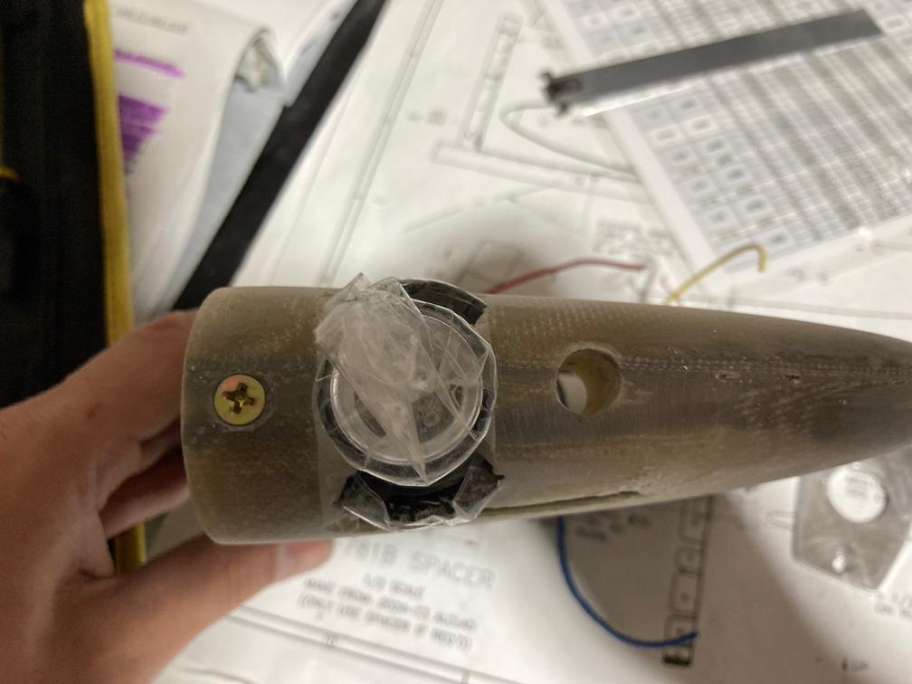
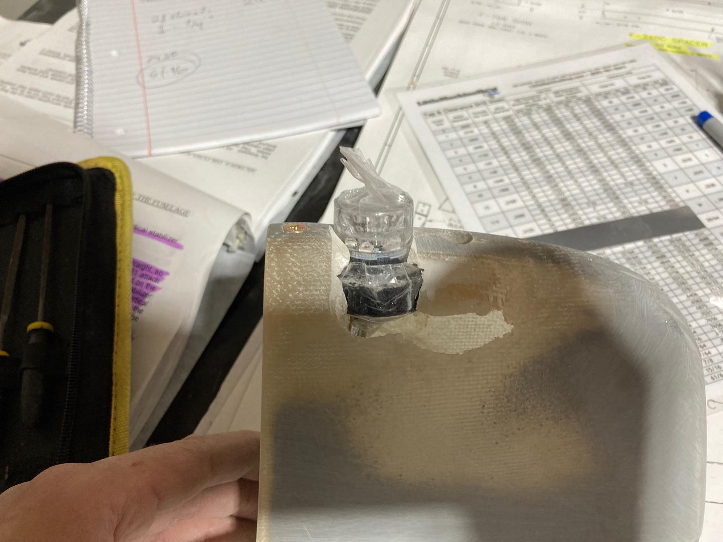
This is what it looks like from the inside.
![]()
It's not pretty, but provides a good seating area for the beacon. I planned to cover two sides later, filling them with the epoxy flox from the inside and covering them with some fiberglass cloth from the outside.
However, this is where I made a couple of mistakes. First, I managed to break off one of the screws -- it got stuck in the insert due to some remaining epoxy. Second, while removing the beacon, I broke off one of the epoxy flox seating areas from the fairing itself. Most likely due to poor bonding -- it was hard to sand the fairing inside since I had already installed the aft cap at that time and did not have good access for scuffing the area.
While sanding, I found some interesting layer combinations in the fairing. It looked as if some of the fiberglass cloth was glued on top of the gel coat (the gray coat). Or so it seemed. Either way, I had to sand a large area to get to the "solid" parts of the fairing.
This is what it looked like after all the sanding -- a big hole on the side.
I tried to remove the broken screw, but could not. In the end, I drilled out the whole insert.

I decided to upsize the insert holes for the #8 screws, as they are stronger, and also AN515-8R8 is used in many other places.
I don't have photos, but I machined a new insert and upsized the hole in the existing one to #8. I removed the top "retaining" countersunk #6 screw and replaced it with the similar #8 one. Then I glued the new insert into the hole, making sure that the hole was scuffed well and that the aluminum insert was also sanded well for good bonding.
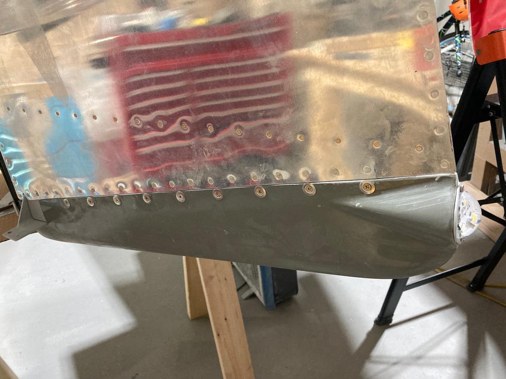
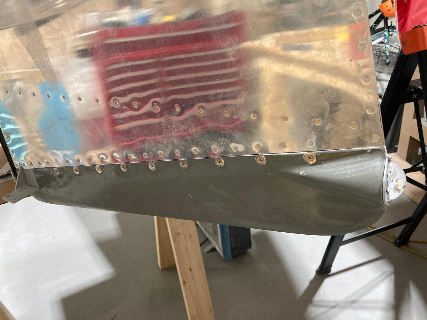
Then I moved back to the bottom rudder fairing. I cut the hole for the tail light, but the light did not fully fit.

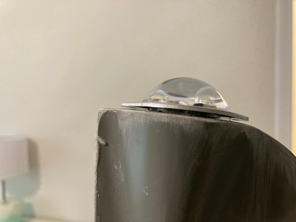
The reason is that the light is not flat, but has a small ring of epoxy.

To make it fit, I ground some recess for that epoxy ring. There is so much epoxy flox in the fairing aft area that I was not worried about the strength. Probably, a bit too much.

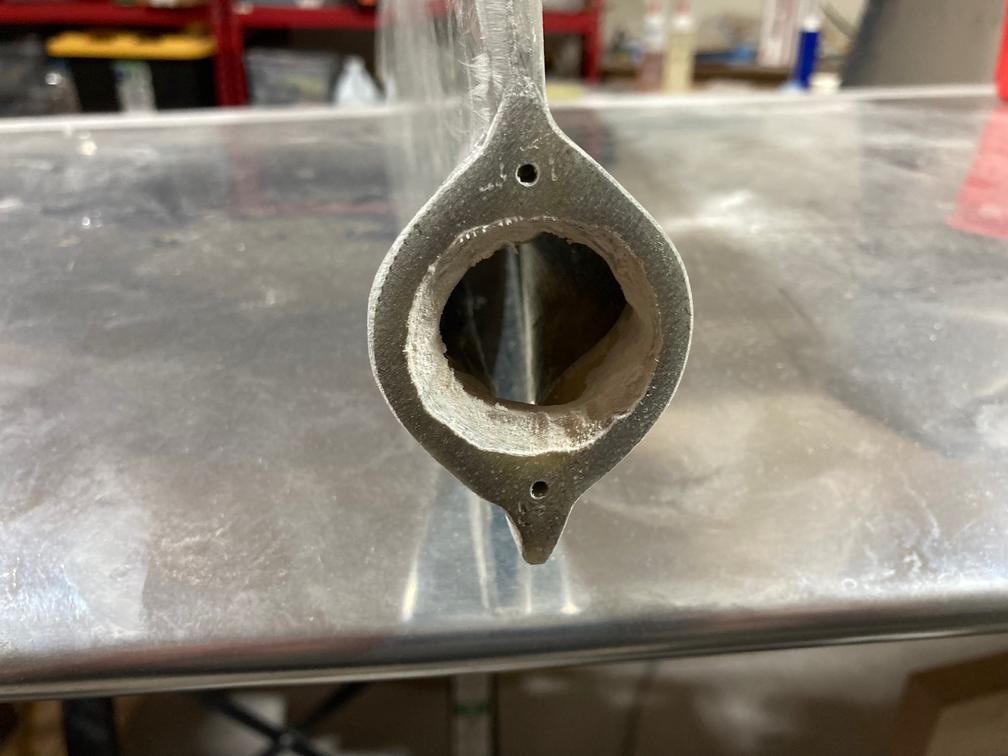
Finally, I worked a bit on mounting the bottom rudder fairing to the rudder. There was one extra hole I drilled in the rudder spar to mount the front part of the fairing. The hole is not on the plans, but I didn't even think about it. However, later I found somebody mentioning that they wouldn't put a hole there (I'm not the only one to put an extra mounting hole there) since these flanges of the spar transfer the load up the rudder.
I asked Vans' support, and they said that this was okay.
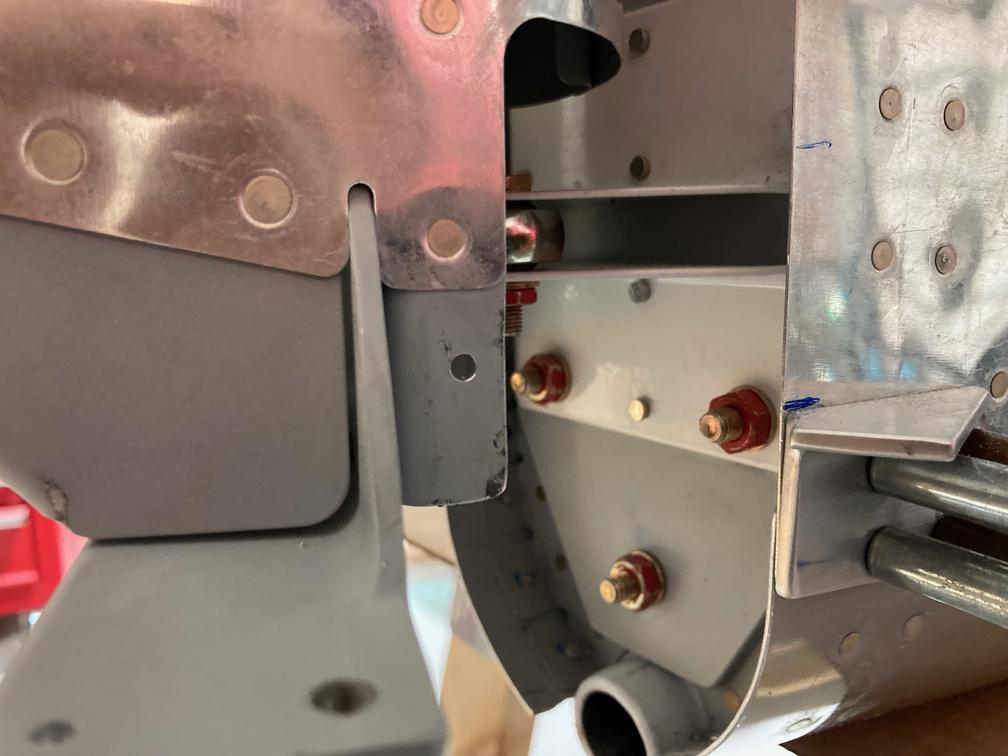
The hole in question.

I am going to use a ClickBond nutplate there just so I don't have to drill more holes in that spar.
Then I installed all the nutplates for the screws. I did not stagger the aft nutplates (or, more precisely, I did, but not enough), so I had to shorten the screws a bit so they fit. Also, I was debating if I wanted to add one more hole into the horn brace.
I looked at the RV-14 rudder instructions (which are very similar in construction), and they do put one hole in that brace, so I might do it as well. I'll probably use the same ClickBond nutplate there.
The reason I was looking at the RV-14 plans is that I was considering replacing my rudder with an RV-14 one. It has the same form factor, but seems like it has a better internal design (all the stiffeners are tied together, and to the spar to form "ribs"). Will see. I might do it later.
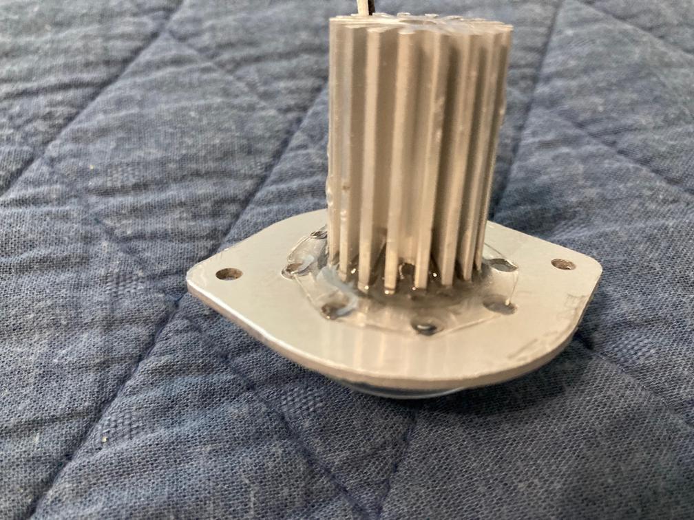
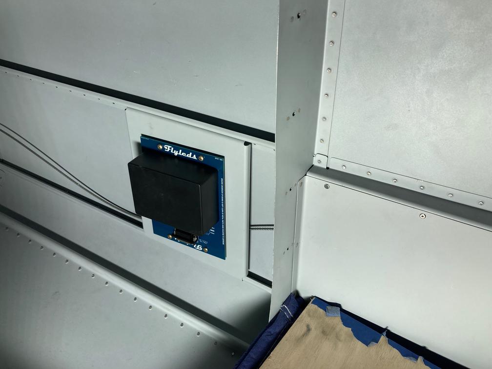
And, at the very end, I put the FlyLeds controller into its designated location. All the holes matched just fine, and the box I bought for it fits perfectly (the box name is specified on the controller PCB -- good job, Flyleds!).